Tamiya 1/16 Pz.Kpfw.V Sd.Kfz.171 Panther Ausf.G Full-Option Build Review
By Michael Benolkin
| Date of Review | September 2007 | Manufacturer | Tamiya |
|---|---|---|---|
| Subject | Pz.Kpfw.V Sd.Kfz.171 Panther Ausf.G Full-Option | Scale | 1/16 |
| Kit Number | 56022 | Primary Media | Styrene, cast metal, machined metal, aluminum |
| Pros | Easy build, awesome sound system and RC control | Cons | |
| Skill Level | Basic | MSRP (USD) | $1200.00 + Radio and Batteries |
Background
A number of years ago, I was passing by the Tamiya USA booth at the RCHTA Hobby Show in Chicago and much to my surprise, a tank battle was in progress with a number of 1/16 Tiger tanks blasting away at a replica of a T-34. What was interesting was that each of these Tigers had synchronized engine sound with the motion of the tank, different sounds for the drive motors for the turret and gun elevation mechanisms, very realistic recoil, sound and flash from the main gun fire, and even a hull-mounted machine gun that lit and sounded when fired. My wallet started screaming in agony at the sight of all of this and I beat a hasty retreat.
Each year since then, Tamiya has produced a new tank in the series including the M4 Sherman, M26 Pershing, King Tiger, and Leopard 2A6. In addition, they released an optical receiver that drops into the commander's hatch opening and a special laser LED mounted on the main gun barrel that is tuned to the optical receiver. Both are connected to the tanks central computer system. When the main gun is fired, the LED fires at the same target. If the receiver on the target registers three hits (as I understand the programming), that tank is deactivated for a period of time - a kill is scored. MILES gear (for you Army types) or Lasertag (for the rest) battles can be waged against one another (or team vs team) without damaging the sizable investment that makes up this project.
This year Tamiya released the Panther G. While I've been waiting patiently for either the T-34/85 or an M1A2 Abrams, my local hobbyshop suddenly went out of business and they had this Panther G on the shelf for half price. What the heck, my inner child got the better of me.
The Project
The Panther box sat on the floor for a few weeks while I was tied up with the frantic pace at work and using what little time remained to publish daily Cybermodeler updates. Then it happened. Free time! I celebrated by sleeping until the crack of noon, then pondered my workshop whilst ingesting copious amounts of coffee. Do I do the responsible thing and finish the PT-117 build
or perhaps the F-22 paint job? It took several nanoseconds to suppress the guilt and I turned my attention to the Panther.
I had made use of those few weeks to figure out what kind of a radio should go in this beast since the my local hobby shop was now gone. A little research on the internet revealed that Futaba, a trusted name in the radio control hobby, had produced a four-channel radio tailored for the Tamiya tanks and robotics markets. This is the Attack 4WD and I found a good price (and one in stock) at the Tower Hobbies website. I already had the battery packs that go in the tank as well as the quick charger from a much earlier RC car project. I also found some wheel bearings that replace the brass bushings inside the roadwheels on eBay. With all of this stuff together, it was time to embark.
The Kit
Each of these tanks comes in a large box that even has a carrying handle on it. Inside, the parts are very well packaged and my example was in perfect condition. If you're looking for a super-detailed masterpiece, this is the wrong project. I recall seeing one of the aftermarket companies releasing a SUPER detailed photo-etch set for the Tiger I, though I could not imagine anyone going to all of the trouble of replicating all of the buckles, clips and snaps that were in that set on a tank that was going to rattle around and eventually vibrate everything loose. To each their own...
The foundation of this project is the lower hull that comes as pre-formed and pre-holed aluminum. The workmanship is excellent. The rear of the hull, upper hull, turret, road wheels, and surface details are all styrene. The drive sprockets, suspension arms and other key mechanical parts are either cast metal or machined. The main gun barrel is also machined aluminum. The torsion bars for the working suspension are steel. Then there are the computers, sound generator, and motors. The track links are all pre-assembled and even in a usable color. Simply insert one track pin in each track and adjust the track tension. In other words, this a well engineered project.
Construction
Step 1 assembles the two tension pulleys that allow you to adjust the track tension using two screws protruding under the rear hull. Each pulley assembly is ten parts that all come together at once, but this step is a quick glimpse of the steps to come. This step is not difficult, it just requires patience and adequate working space. You also become acquainted with Tamiya's thread lock which helps to keep screws, bolts, etc., from vibrating loose later on. Pay attention to the instructions as they clearly show where to use the thread lock, don't use it where they don't indicate.
Step 2 installs the suspension arm bushings into the lower hull. This takes a little time and lots more thread lock. Here is where I came up with a way to speed up this process. Apply a drop of thread lock to the tip of your Phillips screw driver, then put the screw on the screwdriver. Add thread lock to the screw threads and install. While my screw drivers are magnetized, the drop of thread lock really kept the screw in place until it was safely threaded into the bushing. I didn't loose a single screw to the carpet monster and this set went by rather quickly. I removed any remnants of the thread lock from the screw heads and hull using lacquer thinner on a cloth
In Step 3, we install the torsion bar mounting rails to the lower hull, also using thread lock to secure the screws in place. Study the installation drawings for the tension pulley assemblies as there is an interesting mix of parts. This is the first step installing Allen screws and I used the same trick - a drop of thread lock on the Allen wrench - to keep parts from dropping off the tools before installation. Worked like a charm!
Step 4 was interesting. You install the steel torsion bars through the hull rails, then install the corresponding torsion arm over one end while twisting the arm to align the keys to the slots in the hull bushings, then pushing and locking the suspension arm shaft into the hull. The first one took a little experimentation to understand, but once you get the suspension arm through the hole/slots in the hull, the torsion bar snaps the arm to the neutral position and is fully articulating after that point. One by one, I install each suspension arm, but many of them don't want to slip into position. As luck would have it, I have a very small hammer with a rubber mallet head on one side. I used the mallet to tap the arms into place where they snapped to their neutral position. Don't use a heavier hammer nor a hard-headed hammer as you might damage the suspension arm.
Steps 5 and 6 add the electronics tray inside the lower hull and the remainder of the track tension mechanism that adjusts the position of the track return rollers. Step 7 assembles the first styrene parts with the two mufflers and the jack that is stowed on the rear of the tank.
Step 8 installs the twin drive motors into the lower hull, one for each set of tracks. Take note that they are installed in one order only - Left Gearbox, then Right. If you do it backwards, the Left Gearbox will not install.
Step 9 assembles the styrene rear hull with the mufflers, jack, and fittings. This assembly is mounted to the rear of the aluminum hull in Step 10 and now the Panther is really starting to take shape!
Then there is Step 11 and this is where I started came to a screeching halt. There are eight sets of road wheels on each side of this tank. That makes for 32 individual wheels since each set is made up of a pair of wheels. The wheels are molded from styrene, but each one is fitted with a rubber tire. Tamiya cast these tires with a rubber "sprue" and you must cut this sprue from the inside of each tire, connected all the way around the tire 360 degrees. I pulled out my trusty X-Acto knife, started one cut, replaced the blade with a new one, and resumed cutting. The sprue is thinnest where it meets the tire, so if you can keep your cut along that edge, it isn't too bad, but I wasn't in the mood to cut 31 more tires - the project was put away for the evening.
The next day, I was fired up about something and needed something to work out my frustrations. I must say that I went through all 31 remaining tires in no time flat. What's more, if you pay attention to where the blade is traveling around that thin channel between the sprue and tire, there is no trimming or clean-up required after removing the sprues. The tires are done!
Step 12 is the assembly of the wheels with include axles and bearings (or bushings if you don't buy the upgrade). Before I can assemble these wheels, a quick look through the instructions reveal that I have gone about as far as I dare without doing some painting. This Tamiya kit is conveniently finished with three colors: Tamiya XF60 Dark Yellow, Tamiya XF61 Dark Green, and Tamiya XF64 Red Brown. I use Dark Yellow as my primer coat. Though the styrene is roughly the same color, the real exercise is making all of the machined metal parts come out the same color as the styrene. With the wheels painted, it was time to assemble the wheels and axles.
- The kit provides brass bushings to allow the wheels to rotate 'freely' on the axles. Tamiya provides some grease to help with lubrication. I have some issues with this approach.
- Even if operated on the cleanest floors, this tank is going to attract dust.
- On normal floors, you're going to get larger particles of sand and dirt in the wheels. If these axles are greased, then the grease will collect the dirt inside the wheels.
- If you don't grease the axles, the brass bushings will create friction on the axles and potentially build up heat depending on how hard you're working your tank. Once again, not a good idea on the wheels and axles.
- Also, the more friction you have in your wheels, the harder the drive motors will have to work to propel the tank and that, in turn, generates heat from the motors and battery pack. Those expensive electronics inside the tank hull are no-doubt rugged, but there is a limit to their thermal tolerance and the cooler you can run your tank, the longer the life of those electronics.
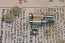
For me, the solution was simple. As with my radio control car project, I replaced the brass bushings with sealed ball bearings. I found Hobby Summit hobby shop in Hong Kong that sells ball bearing kits for this tank on eBay. I placed an order and had my bearings in about a week. You can see in this photo the axles with the brass bushings and the ball bearings side-by-side. While you can't see much difference, the wheels move much more freely now.
I assembled all sixteen wheel units with their axles with my new bearings, but otherwise by the instructions. I didn't use (nor do I need) grease with these bearings. Unfortunately, the return rollers did need grease and special brass bushings, but the return rollers and drive sprockets can be dismantled later. The wheel units are glued together, so servicing these later will be next to impossible.
Step 13 has you install all of the wheel units on each side. Each axle has a keyed flat spot to lock the axle in place with an Allen screw. The hardest part is interleaving the wheels and mounting the axles onto the suspension arms. I took my time here as I installed all of the wheels, spun each one to see if it was rubbing against one of the adjacent wheels, then installed the Allen screw with a dab of Tamiya thread lock. As before, I used a drop of the thread lock on the tip of the Allen wrench to hold each screw whilst maneuvering them into position. Once again, not a single screw fell into the carpet.
Step 14 is only to remove four links from the pre-assembled lengths of track. Simply pull the fourth pin, remove the links, and save them as spares.
Steps 15 and 16 installs the properly lengthened tracks onto the wheels and drive sprockets. I loosened up the tension adjustment screws on the underside of the hull rear and installed the tracks per the instructions. This didn't take any time and then I played with the tension on the tracks until they sagged as indicated in the Step 16 illustration.
Safety note - the instructions are clear on this and Tamiya even wants you to install safety stickers on your hull, but anything (like your fingers) that get caught up in the track and drive sprocket are going to get injured, squashed, and/or damaged. If you're working on the drive system, be sure the tank is switched off (or better yet, that the battery pack is removed). Be careful as these drive motors can really move fast and fingers, clothing, or other things can get caught in the track and pulled into the drive sprocket.
Steps 17, 18 and 19. Step 17 is charging your battery pack. Step 18 is nothing more that loading batteries into your transmitter. Everything checks out fine on my Futaba transmitter. Step 19 is where we connect up the DMD Multifunction Unit and DMD Control Unit together with the speaker module, rechargeable battery pack, and Futaba receiver. The instructions show four labeled lines coming out of the DMD Control Unit and inserted into the receiver in channel order. Unfortunately the channel order is reversed on my receiver, so I put the Ch.1 line into the Ch.1 port on the receiver, ditto with the other three channels.
When all was connected, I powered up the receiver and heard a burst of static from the speaker and nothing else. When I turned on the transmitter however, the Maybach engine turned over and started. I followed the calibration instructions outlined in the Tamiya instruction booklet and then turned off the transmitter. The engine shut down. Too cool. The instructions warn not to connect up the other devices like the main gun flash unit until later as there are still other steps that need to be done to get the electronic units set up properly. Of course I fired up the transmitter again and played with the throttles, gun traverse and elevation and listened to those sound effects. This is going to be fun!
Steps 20 and 21. Step 20 is simply stacking the two DMD units atop one another with double-sided tape and installing two connectors. Step 21 is where it really starts getting interesting. The stacked DMDs are affixed to the aluminum tray inside the hull with double-sided tape with the backs of the DMDs against the right side of the hull. This leaves just enough room on the tray to lay the battery pack.
Connect the drive motors to the corresponding lines from the upper DMD as shown in the instructions. Be sure and get a solid 'snap' connection or they will come loose later. Use some of the nylon cable ties to bundle up the wires as shown. There will be several unused connectors at this stage but don't worry about this now as these will connect up the turret systems later on.
Step 22 continues the process by installing the speaker unit into the rear of the hull, installing the radio control receiver onto the speaker unit, and installing the battery pack. Note: Do not tape or mount the battery pack. Simply lay it on the tray next to the DMDs and connect up the power connector. You'll want to be able to remove the battery pack for easy charging, or to be able to swap battery packs in the field while in 'battle'.
Steps 23 and 24. Okay, you're done with wiring and mechanics for now. Time to get on with some model building. These steps assemble and install details on the upper hull. I elected not to install any of the tools at this stage as I didn't want them to get camouflaged nor did I want to cover up sections of the hull that would get camouflaged.
Steps 25, 26 and 27 continue on the left side of the hull with the hull-length steps, rear deck heating unit, tow cables, headlight and gun barrel travel lock. I opted not to install the tow cables and spare track at this stage.
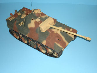
Steps 28 and 29 continue the detail installations on the right side of the hull. It was also time to start laying out the camouflage pattern before we start the installation of the motors and lighting units. Here you can see the Red-Brown laid out and drying before adding the Dark Green.
Step 30 is interesting. Here you take a nicely machined machine gun barrel, attach a brass adaptor, insert a light pipe into the barrel and an LED into the adaptor. This was the first time I had to use cyano in this project. Before installing the light pipe, you need to scrape or sand the sides of the pipe to allow the blinking machine gun to be more visible from the sides.
Step 31 installs the machine gun unit into the bow machine gun port, install the turret traverse motors and wheels around the turret race. Finally, the only soldering job in this project adds an eye to the end of the RC receiver antenna which is connected to an external antenna on the hull.
Step 32 slides the upper hull onto the lower hull, connects the machine gun and turret traverse units into the DMD controllers, and hold it all in place with a retaining screw disguised as an engine vent on the rear deck.
Steps 33 and 34. Step 33 is the assembly of the gun mantlet. Pay attention to how the parts are oriented or you might have to start over again. Step 34 brings us to the beautifully machined main gun barrel in aluminum. I primed this with Dark Yellow, then installed the flash unit as indicated in the instructions. This is mated up with the mantlet and a recoil motor. This assembly also has the only servo link in the project that connects up the main gun frame with the elevation motor to be installed soon.
Step 35 simply installs the rear plate of the turret, the commander's hatch, and a mount that can be swapped later for a connector for the battle sensor modules (available separately).
Step 36 mounts the main gun to the turret. I am a little puzzled here as the main gun is rather heavy, but there is no screw-mounting of this mantlet assembly to the turret - just glue. It may be fine, but my instinct tells me that this will be a recurring problem with glue alone. Do NOT use cyano here as that will break away under duress. I used good old-fashioned Testors Liquid Cement on this job as it will provide the strongest and more tolerant join.
Step 37 assembles the traverse ring and elevation motors to the turret bottom. This assembly is mounted to the rest of the turret with four screws.
Steps 38 and 39 add the finishing details to the exterior of the turret.
Step 40 mounts the turret onto the hull and connects up the remaining electrical connectors.
The Moment of Truth
After bench-testing the DMD units, I was ready to see if this beast would work as I had seen at the trade shows. I switched on the main power switch on the rear of the hull and set the tank on the floor. As appropriate, it sat quietly. When I switched on the transmitter, the Maybach engine turned over and barked to life. There it was, sitting there idling and waiting for my commands.
First thing was the drive. It will take a little getting used to controls, but the tank moved smoothly on carpet and on hardwood floors. Turning was not a problem moving forward or reverse.
The turret moved left and right with the appropriate sounds, but the gun didn't elevate. A quick look in the turret revealed that I forgot to install the linkage arm between the gun frame and the elevation motor. That was easily remedied with a long hemostat so I didn't have to dismantle anything. Retesting the unit and the gun elevates on command. Let's go shooting!
The instructions show that with the elevation trim in neutral, nothing will happen other than moving the main gun up or down. Slide the trim full-up and snap the stick up and release, the main gun fires. BOOM! Nice sound! Not only does the gun fire, that flash unit in the barrel flashes brightly, the gun recoils into the turret and moves back into position, and the hull even lurches backwards in recoil. Those DMD units are nicely programmed!
Slip the elevation trim full down and quickly move the elevation stick downward and the bow machine gun fires. The machine gun sounds out smartly over the speaker and the LED blinks in unison out the end of the machine gun barrel. The machine gun continues to fire as long as you're holding the stick down.
According to the instructions, the unit comes pre-programmed to only allow the main gun to fire no more that once every nine seconds. You can change the switch settings to once every three or five seconds. There are two different options in the nine-second rate, one for large gun recoil, one for small recoil. I switched my options to once every three seconds.
Time to hunt cats. As my wife watched, we saw two different reactions among the cats. The ones who've been here a while simply watched (Buddy, the Norwegian Forest Cat, actually yawned as the tank passed him). The kittens didn't know what to make of it so they headed to higher ground. Oh well, the tank failed the cat test...
Final Touches
With the tank completed, it is time to go back and fine tune the camouflage (and paint those parts that were installed after the last camouflage session. The whole airbrushing job was done with my trusty Iwata TR2 airbrush
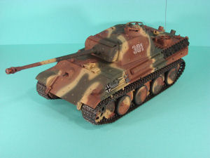
which has the ability to work down to finer feathered lines and still cover larger areas with just a pull of the trigger. When the three colors were laid down and dry, I shot a coat of Future acrylic through the TR2 on the areas where the decals would be placed. When the Future had dried, I applied the decals with Tamiya Decal Softening Solution and let the chemestry work its magic. The decals had laid down with no silvering. Another coat of Future blended the edges of the decals into the surrounding surfaces, then a coat of Gunze Sangyo acrylic Flat Clear removed all evidence of the gloss coat.
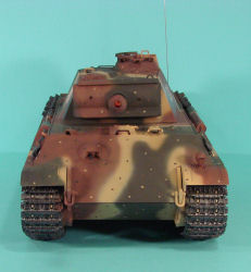
Next came the paint brush, the three main colors, and the paint guide. Color-by-color, spots were applied to the camouflage and the effect is quite interesting. Once again, this was all set aside to dry. The spare track links and pioneering tools were painted next and installed on their respective stowage racks. The only things not yet done are installing the tow cables and applying some weathering.
Conclusions
As you can see, the Panther has lots of fun potential. I really can't see spending much time or expense with photo-etched details when this tank is going to get jolted and bumped in 'combat', the hull is going to get flexed as you pick up the tank or remove the upper hull to access and recharge the battery pack, and any of these actions will quickly cause cyano-type glues to fail. If you want a super-detailed Panther, buy a static kit. Keep this gem around for fun!
Any of the tanks in this Tamiya series are highly recommended. I've been impressed with these as I see them at the hobby trade shows, and now that I've built one, I can honestly say that any modeler can tackle one of these projects with a minimum of fuss. It is definitely not a weekend build, but it only took me approximately 24 hours (not counting drying time) to complete.
You can see and listen to a brief demonstration of this model on YouTube here.
