Italeri 1/35 Elco 80' Torpedo Boat PT-596 Build Review
By Michael Benolkin
| Date of Review | January 2007 Updated May 2015 |
Manufacturer | Italeri |
|---|---|---|---|
| Subject | Elco 80' Torpedo Boat PT-596 | Scale | 1/35 |
| Kit Number | 5602 | Primary Media | Styrene |
| Pros | The nicest kit Italeri has ever produced!!! | Cons | Camouflage color call-outs are not all correct |
| Skill Level | Intermediate | MSRP (USD) | $149.95 |
Background
For some background on the Elco PT Boats and a look at the Italeri kit as it comes out of the box, check our in-box review here.
The Kit
Once you get past the size of the kit, you just apply the same logic, skills and tools to assembling this model as any other. You just need a bit more real estate on your work bench!
Essential Tools
To take on this job with the least amount of frustration, one must have the right tools. While you can use just about any type of cement on this project, I like Tamiya's Extra Thin to get into the spots I need covered. To get the cement into the delivery spot without leaving glue goobers on my paint (or worse), I use the Touch 'N Flow applicator, which is a glass pipette with a needle mounted to one end. Simply add glue and you can apply it with precision.
For my tired eyes, I won't do any project without my beloved Optivisor. I didn't think this could get any better until I discovered the Quasar Lighting System
from Novacon Ltd. This interesting device simply snaps into place over your lenses giving you a bit of a classic 'Elton John' look, but there are six bright white LEDs that illuminate along your line of sight. Perfect for working in tight spots.
Of course there are the usual necessities, the Xuron styrene cutter for removing parts cleanly from the sprues, a typical pin vice and micro drill bits, a toothless hemostat for cleaning up photo-etched parts, an X-Acto knife, tweezers, and micro-files for working with styrene parts.
Last but not least are my favorite airbrushes, both from Iwata. First is my Revolution TR2 for covering larger areas, and the other is the Hi-Line HP-AH
which gets small quantities of paint into precise places - perfect for touch-up work. The Skybow SP100 is another good airbrush for touch-ups, but lacks the precision air control of the Iwata.
Construction
Taking the job on as described in the instructions, Step One is dedicated to drilling out all of the relevant holes that are flashed over on the surface of the main deck. There are more holes than needed for this project, so as I thought in the in-box review, there is at least one more version of the Elco 80' boat coming in the future. Care was taken to open the holes with my handy pin vice, then come around the other side with a Dremel bit and manually remove the excess styrene from around the new holes. The tree molded into the center of the main deck was also carefully removed.
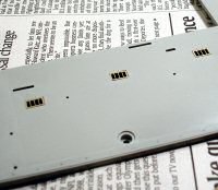
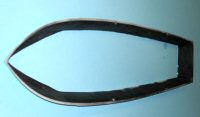
Step Two is where I stopped and pondered. The instructions have you install the acetate clear windows and photo-etched frames into the surface of the main deck, then add a few styrene parts. The problem I had was trying to figure out the best way to use those acetate windows since they'll need to be masked off to paint the deck, or if I paint the deck first, I'll still have to paint the photo-etched frames.
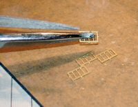
When I removed a set of the photo-etched frames from the fret, I dropped one into the recess in the deck and realized that the recess may not be deep enough for the frame and the acetate window. The decision was made to leave off the acetate and install the frames.
I use a toothless hemostat as a photo-etch vise so that I can file away the remaining fret attachment points without bending the part. I installed each photo-etch frame with thin cyano cement. When they were all in place, I used Mr. Dissolved Putty around the frames to close the gaps between the deck and frame. When you look at photos of the main deck, you can hardly see these flush-mounted skylights and definitely cannot see the frames not flush with the deck surface. So what am I going to use for glass now that these window frames are installed in the decks? Wait for it...
As I continued to ponder the final appearance of the kit, I decided to do some 'field research' and popped a DVD of 'They Were Expendable' into the player and took a look at the boats in the film. While these were not really representative of late-production Elcos, I had the inspiration and ideas I needed to push on. With deck-mounted skylights and side windows mounted into the deckhouses, I could paint them from behind to represent black-out curtains or leave them clear. If I leave them clear, the observer would see into the great abyss inside the that gray styrene hull. The answer to that was simple enough, paint the insides of the deckhouses, main hull, and even the light shafts under each photo-etched grille flat black. You'll still be able see out another window or opening, but the black will render hide the emptiness within.
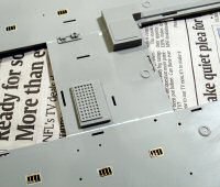
I wet-sanded the deck surface to remove any excess Mr. Dissolved Putty and blend the photo-etch frames into the deck surface. It was time to install the various styrene parts. First up are the deck railings around the bow. Absolutely no issues here. Next is the bridge deck plate that spans across the rectangular hole in the main deck. The deck plate is a bit too narrow for the job, so I mounted it firmly to the starboard side and clamped it tight around the electrical junction box mounted on the deck and deck plate. This left a gap on the port side that was filled with strip styrene and Mr. Dissolved Putty. When dry, everything was sanded smooth.
Now it is time to paint the main deck. Thanks to a heads-up from John Snyder of White Ensign Models AND Snyder & Short paint chip fame, it was clear that the paint call-outs in the instructions are a bit suspicious. The instructions call for Pale Green for the main deck and I was eyeballing a bottle of that color when John's email came in. The reason I was suspicious in the first place were the photos of PT-596 that were provided in the little reference book included in the kit. The deck is clearly dark (faded, but dark) in those shots and something just wasn't right. I took my copy of the PT-596 reference included in the kit and had a nice session with my scanner and imaging software. I scanned each of the three black and white images of PT-596 in the book and expanded them so that I could really see what I was missing. Enjoy!
Al Ross had confirmed that PT-596 was painted in Measure 31/20L. A quick cross-check of the diagram Al sent over with the kit instructions show that the pattern in the instructions are correct. Just the greens are mixed up and the correct colors are:
| Kit | Correct | |
| Deck | Pale Green | Deck Green 20G |
| Camo 1 | Pale Green | #2 Green |
| Camo 2 | Medium Green | #3 Green |
| Camo 3 | Flat Black | #82 Black |
| Undersides | Flat Red | Copperoid or USN Anti-Fouling Red |
Thanks to Al Ross and John Snyder for the assist!
When I put the original color tables together for this project, we hadn't developed our current (2015) digital color-matching system. Now that I'm overhauling my previous work, I find that the color options are also worth another look as well. Since the original build, a number of colors have also come onto the market which provide some nice options. Aside from my original choice for #3 Green, I was pretty close color-wise though there are even closer matches available now:
| USN Color | Accurate Options: | I used in 2007 build: | I am using in 2015 rebuild: |
|---|---|---|---|
| Deck Green 20G | Gunze N/A | Gunze H65 Black Green | Vallejo 607 UK Bronze Green Primer |
| Humbrol 195 Chrome Green | |||
| Tamiya N/A | |||
| Testors 4780 RLM 70 | |||
| Vallejo 607 UK Bronze Green Primer | |||
| WEM US16 Deck Green 20G | |||
| #2 Green | Gunze N/A | Tamiya XF65 Field Gray | Tamiya XF73 Green JGSDF |
| Humbrol 117 US Light Green | |||
| Tamiya XF73 Green JGSDF | |||
| Testors 4781 RLM 71 | |||
| Vallejo 71.104 Green | |||
| WEM US23 #2 Green | |||
| #3 Green | Gunze H302 Green | Tamiya XF62 Olive Drab | Gunze H302 Green |
| Humbrol 91 Black Green | |||
| Tamiya N/A | |||
| Testors 4729 Europe I Green | |||
| Vallejo 71.021 Black Green | |||
| WEM US24 #3 Green | |||
| #82 Black | Gunze H12 Black | Tamiya XF69 NATO Black | Tamiya XF69 NATO Black |
| Humbrol 33 Black | |||
| Tamiya XF69 NATO Black | |||
| Testors 4768 Black | |||
| Vallejo 71.057 Black | |||
| WEM N/A | |||
| #65A Red | Gunze N/A | Not in my notes | Vallejo 70.982 Cav Brown |
| Humbrol N/A | |||
| Tamiya N/A | Testors N/A | ||
| Vallejo 70.982 Cav Brown | |||
| WEM US14 Antifouling Red | |||
| Interior | Any Flat Black | Tamiya XF12 Flat Black | Vallejo 602 Black Primer |
So, back to painting. The main deck received two coats of paint. Since I am going to weather this model, I want a good solid coat to work with. Once the deck was dry, it was time to address those deck-flush skylights. I had a bottle of Microscale Crystal Kleer handy, but good old-fashioned white glue will do the trick as well. I used a toothpick and rubbed a drop of the fluid around the edges of each window opening. This should leave a white coat closing off each window opening. Don't worry, once this stuff dries, it dries clear. When all was dry, I applied a drop of Future acrylic floor wax on both sides of the window to seal up the transparency. This isn't really necessary, but something I like to do.
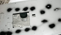
It is interesting to see your model from the literal eye of the digital camera. After two coats of the deck green, the first photo above reveals differences in coverage while the second doesn't - it is merely reflecting light. The variation in color might be a bad thing if you're doing a pure museum model, but this actually works well for this project since this will add to the wear and tear that will get weathered into the deck surface later. All of that completes Step Two. Whew!
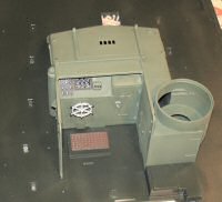
Step Three is the bridge/pilot station, forward deck house, and forward machine gun mount. Now that the colors are sorted out, things move on a little quicker. I pre-painted part 43 so that I can install the engine instrumentation, throttle quadrant, and switch panel to the face. The ship's wheel is also installed at this point.
The forward deck house goes together nicely, but mind a hint of flash here and there that will affect the fit of these parts. Dry-fit everything to make sure that not only you understand how everything comes together, but that the parts don't have a subtle bit of flash that would hinder a proper assembly. Following the instructions, I assembled the parts as shown and used Tamiya Thin Cement to put it all together. Once I was happy with the results, I did a quick test-fit on the main deck to ensure no surprises, then applied Mr. Dissolved Putty on the various seam lines. Once again, once it was dry, quick wet-sanding blended everything nicely together.
As the rest of this project will reveal, you build a little, then paint a little. I applied my base color of #2 Green to the deck house and allowed the paint to dry. I decided to start detailing out other areas in the interim. The cable runs that extend from aft of the forward turret to the rear of the main deck was masked and painted Medium Gray. This is definitely not what they likely were in reality, but it is time to add some subtle detail to busy up the deck. The grating that the helmsman stands upon was painted Red-Brown. Both the cabling and grating were given a wash of Lamp Black oils to dull down the colors and bring out some of the molded-in detailing. I dry-fit the deck house when all was dry.
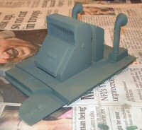
In Step Four, the engine room deck cover and ventilation ducts are assembled. The kit comes with a nylon grating for the intake vent that needs to be cut 32.5mm x 12mm. A quick check with my calipers confirm the size and the grating was cut with my X-Acto knife and installed with thin cyano. The ammo rack that mounts aft of the intake vent and between the exhaust ducts is assembled and installed as well. I used Mr. Dissolved Putty to remove the seamlines inside the mouths of the exhaust ducts. When this was all cleaned up, I painted the completed assembly #2 Green and set it aside to dry.
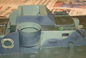
Step Five brings together the mid-ship deck house that also incorporates the aft 50 caliber gun mount. There were no issues here other than to paint the completed assembly #2 Green and the interior Flat Black as the windows will be exposed in this assembly as well. Since Step Six has us install the three deck house assemblies to the main deck, it is time to catch up on some paint work.
While cross referencing the painting diagrams in the instructions and the enlarged photos of PT-596 above, I airbrushed Green #3 into place on all three assemblies. The color really isn't used much on the deck houses, but will be a little more visible on the hull later. This is followed up with the NATO Black. When all this had dried, I masked off the horizontal surfaces and applied Deck Green 20G.
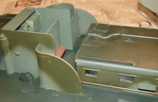
After the basic coats of camouflage had dried, I painted the cable run that extends over the top of the center deck house the same gray as the cable run on the main deck. I painted the handles of the two hook poles that are stowed on either side of the central deck house Red Brown and the mounts the same as the background camouflage colors. These were mounted along with the railings atop the roof. Again, the bare wood is not likely how they were kept in the field, but they do look nice. The ammo rack on the rear of the engine room cover has a nice canvas-textured cover that I painted a different Olive Drab followed by highlights of Buff. All of this still remains subtle, but it does busy up the colors on the deck.
The final preparatory step is to install the acetate windows. These are cut ever-so-slightly too large, but they were wedged into place with a Q-Tip so I wouldn't scratch the window during installation, then cemented into place using Tamiya Thin Cement applied with a Touch-N-Flow applicator. At last, we're ready to move on!
Step Six - mount the three subassemblies to the main deck. Simple, right? Not so fast. I found that the best approach to installing these was one at a time, and even then, just a section at a time. The main deck bows under its own weight, so in order to get a good tight fit, I cemented one wall at a time and then clamped that edge down to the deck. While this was a bit time consuming, the result is a solid structure upon which lots more parts are added in the coming steps.
Step Seven - time to install the wooden bench seats onto the armored shield that mounts behind the pilot station. These benches are textured wood, so I couldn't help but take a little more license and paint these Tamiya Red-Brown as they'll be shielded from view. The side shields that mount to the rear sides of the forward deckhouse. These have reinforcing brackets made of photo-etch that also get installed now. While we're on photo-etch, a set of steps are also provided, on to step up onto the forward deckhouse and one for the mid-deckhouse. While the forward step is installed here and the mid-step doesn't install until step 14, I opted to install both while we're at it. Once everything is in place, I airbrush the appropriate colors to bring the new parts into the camouflage scheme.
That's when I noticed the life rings that hang outside the new armored shields. The color call-out in the instructions says orange. Let's just say that we didn't go to all of this trouble to camouflage our boat just to put orange bull’s-eyes on the sides of my boat for the Japanese gunners to track. These life rings are another opportunity to 'busy up' the boat. I selected Tamiya NATO Green for the rings, a Gunze Olive Drab that doesn't match the OD that I'm using for my camouflage, and Tamiya Buff for the ropes. The new OD color is used to replicate the binders that hold the rope around each ring. These colors are subtle and do not stand out to violate the camouflage, but when viewed closely, they provide the viewer with nice eye catching details to 'busy up' the boat.
Step Eight - here is where we start adding antennas and such, that means more care will need to be taken around the model since the single sweep of an arm can clear away these details unintentionally. I shot all of the antenna masts and spotlight Green #2. The photo-etched antenna elements and the vertical element are all painted gray. I thought about putting an MV lens into the spotlight, but instead I painted the inside of the light black and installed the kit's acetate lens. It has a nice effect.
Photo-etched shields are installed atop the forward deckhouse to block off the navigation lights except in the directions they're supposed to be seen (when not in combat). The instructions got this backwards. Red is supposed to be on the port side (left), green/blue on the starboard (right). Green and blue are used interchangeably on nautical and aviation navigation lights.
Step Nine - the main part of this step is the lifeboat. This mounts atop the roof of the forward deckhouse. The instructions call for Light Ghost Gray and they got that right - I assembled and painted the lifeboat halves gray, but this is another opportunity to busy up the boat with some subtle details.
I painted the internal frame of the boat Tamiya German Gray, the rope retainers OD Green, and the rope surround outside the boat as well as the rope that hold the internal frame to the float all Tamiya Buff. The bucket is Flat Black, the oars are Green #2 with wooden handles. I painted the underside of the lifeboat as well.
Step Ten - here's where we build-up the first tubular structure on the boat. This looks like a roll bar mounted atop the rear engine house, but that certainly wouldn't do any good in the event that the boat rolls over. I'll show you what it does in a minute.
First, this is a six-piece affair that I pre-painted #2 Green because you'll note how difficult spraying is now in these close confines. With everything ready, I cement the main frame (16D) into place followed by the handrails (93E x 2). The three reinforcing braces from the engine room air intake complete the assembly. If ever there was a job for my Touch 'N Flow glue applicator, this was it!
Now for the reason for the frame. We're going to mount a big 40mm BOFORS cannon aft of this frame. The gun can be rotated 360 degrees and elevated to near vertical. To keep a gun crew that is target-fixated from blasting an essential part of the boat, let's say the pilot station, you'd need some way to block the barrel from aiming in the wrong direction. You can see through the frame where the BOFORS barrel is blocked. While it looks like the forward machine gunner might be in the permissible line of fire, don't worry, my camera was higher than the gun would be so the BOFORS would be able to shoot over the forward gunner's head.
Step Eleven - I have been debating how best to display this model after completion. While I am certain that someone is going to develop a nice wooden stand for this model, and many people might be happy with the plastic stand provided in the kit, I want something a little different. To keep the cats from knocking the boat off its stand, the best defense was to mount the boat directly to a diorama base. I am going to depict this boat tied up to a pier.
Now there are two ways to do this:
- The easy way
- The hard way
The easy way is to simply prop the lower hull up on blocks, build up a frame around the outside of the base up to where the waterline would be, then fill the resulting cavity in with clear resin (after some other prep work, naturally). The down side to this approach is that it would take some time to carefully add layer after layer of clear resin to reach the waterline on the hull. Pour too much resin in at one time and the resulting heat from the curing resin would melt the hull. Assuming that I successfully make it up to the waterline, the base would be quite heavy, not to mention the expense of all of that resin!
Which brings me to the hard way - convert the kit hull into a waterline hull. I pondered that approach for a while and came up with an idea. I have a laser level I picked up from a hardware store that you use to put a line on a wall to get a vertical or horizontal reference line. I'll use this to mark a cut line on the hull.
The kit provides a good waterline reference at the stern, but the one for the bow was going to be a real pain to mark off from their reference line. Then a blinding flash of the obvious struck me - the waterline at the bow was just a few millimeters below where the photo-etch reinforcement plate attaches. I laid the photo-etch part into place on the hull and marked a spot in the appropriate place. Next, I moved the bow and stern reference marks down about 5-10 millimeters - this is where I cut. I aligned the laser to the bow and stern reference marks and drew a cut line along the nice bright red line. Repeat on the other side.
I used a cutting wheel in my trusty Dremel to cut just below the cut line. I allowed the cutting to get a bit hot and the molten styrene laminated itself to the outside of my hull. No problem, I was planning a little body work anyway. With the underside of the hull cut away, I trimmed up hull knocking off the big pieces with the cutting wheel before moving to the sink and doing some wet-sanding to clean up the edges. I used the sanding sticks to remove and buff smooth the areas marred by the hot styrene. It was time for the moment of truth - a flat surface!
The hull sits just right on a flat surface. Once I mount it to a base, I'll use gap-filling cyano to close up any small gaps before laying down the clear resin for my water surface.
Don't try this unless you've got the right tools and experience to perform these modifications because you're otherwise putting the hull of your $150 model at risk.
Once the bottom edge of the hull is cleaned up, I install the photo-etched front shield and the styrene frames that divide the sides and bottom of the hull.
Step Twelve - Someone had the great idea that you could submerge the exhaust stacks from an engine and make the boat quieter. While it looked better on paper, the designers had to still put exhaust mufflers inline with the underwater exhaust in order to quiet the engine noise effectively. Anyone with experience with car engines knows that backpressure in your exhaust will decrease your available horsepower, and while mufflers alone will create backpressure, submerged mufflers really create backpressure. So if you look at the rear of the PT boat, you'll see all six of the exhaust stacks (two for each engine) exhaust straight out of the rear of the hull, but for covert (low speed) operations, the butterfly valves at the ends of the exhaust stacks can be closed to redirect the exhaust down through those mufflers. Okay, so now you know what we're looking at here.
Installing the mufflers to the cut-down hull posed a minor challenge since the lower ends of the mufflers attached to a hull that isn't there anymore. To maintain the spacing from the hull and to provide a solid anchor point for the mufflers, I added a strip of Evergreen styrene behind each set of mufflers right along the bottom of the cut hull. With the mufflers installed solidly to the hull, I pulled out the cutting wheel again and removed the lower sections of each muffler that extended below my hull cut line. We'll come back and weather/rust the mufflers later.
Step 13 - Installation of the propellers, shafts and rudders - not applicable.
Step 14 - Pay close attention to these diagrams as we're now getting call-outs for subtle little details like handrail part 40D. I install the forward gun footrail amd the pair of forward deck hatches per the instructions. Gun mount 1F will stay off until later. This is where the instructions want the deck mounted to the hull and the hull onto the stand. This is a good idea with the small detail work that is coming, but I am skipping this step for now as I need the hull separate to mount to its waterline base later.
Step 15 - The machine gun mounts - Italeri has gone to a load of trouble to make the mounts rotatable after installation, but one bit of glue flowing around some of the parts holes will gum up the azimuth rotation very quickly. I seriously doubt you're going to want to play with this boat after going to all of this trouble to detail the model. The guns also move in elevation, but if you follow these next steps, I'd suggest selecting a pose for the guns and sticking with it.
The gun pintle halves go together first and then the gun tray part 51E slides over the mount. I would suggest sliding 51E onto the pintle as indicated, but do NOT glue it until you install the guns as you may otherwise face some fit problems. The rest of the gun mount goes together smoothly until you get to the ammo belts parts 58E. You're supposed to insert the ends of the styrene ammo belts into the breech guides (parts 71E) and then bend the belt down to extend into the opening of the gun mount.
Many folks will be happy with this, but I had just fiddled with the ammo belt guides (parts 56E/57E) that route the ammo belts from the ammo trays to the breech guides. For whatever reason, these parts are ignored after assembly. I decided to do something a little different. I grabbed four sections of Eduard's 1/35 50 caliber ammo belts
and installed one end into the breech guides and routed the other end through the ammo belt guides and into the ammo trays. The result looks a little better to my eye.
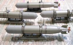
Steps 16 & 17 - Port and starboard torpedo racks and Mk.XIII torpedoes. The racks are quite nicely detailed and I've decided to depict the forward racks empty as the boat will be depicted pulling up to a pier to refuel and rearm. Take a good look at your reference photos as the rack colors are different from each other - on the three PT-596 photos I've posted near the beginning of this article, the port forward rack appears black whilst the other three actually appear to be gray. Excellent! There's nothing like having a little difference in your details to busy up the appearance of the model further.
As you can see in the photo above, the Mk.XIII slips into place on the rack, but the racks are nice enough to leave empty. The photo-etched fins for the torpedoes appears to be a nice touch, but these are parts that could have been rendered in styrene and as noone would notice the difference after paint was applied.
Once the torpedoes were assembled and the seamlines filled, I painted the machined body of each torpedo with Tamiya Titan Silver. This is an interesting color as it appears to have a touch of brass coloring in it and creates the look I was wanting for the machined body. The warhead was painted Tamiya Sky Gray. The bolt holes and joints were given a light wash of Lamp Oil Black to bring out the details a little. Two of my torpedoes will be on dollies on the dock ready for reload whilst the other two will be in the rear racks of the boat. These will get further weathering with Tamiya Clear Smoke to create a bit of oxidation discoloration.
The racks will be installed at a later point as the rear racks actually cover two screw holes for securing the deck to the hull. Since I won't be installing the deck until my hull is mounted securely on its new base, these will be set aside. I'll also install the torpedo propellers at that time as well. In the meantime, the hull as received its primary camouflage though there are still weathering steps to come.
I've had a few requests for the color pattern on the rear of the hull since the instructions don't address this area. Here is the pattern that I have for the job:
I hadn't noticed that I had assembled one the of the torpedo racks backwards, so I carefully dismantled the erroneous torpedo rack and reassembled the unit with everything properly oriented. I'm not sure who came up with the bright idea for photo-etched torpedo fins, but I've come close to replacing them with styrene fins cut from thin sheet plastic using the photo-etch fins as masters. At any rate, the fins are back on the torpedoes, the paint is touched up, and I used some Gunze Gundam markers to add some detail to each torpedo. I assemble, paint, and install the contra-rotating propellers on the torpedoes and we're done! Not so fast...
Just as I am about to claim victory and move on, I noticed that I haven't added the tie-down straps to anchor the torpedoes in place. No problem, right? I then realize that the fine individual who conceived the photo-etched torpedo fins also conjured up the torpedo tie down scheme - you're given silver (or aluminum) wire pre-cut to length but still bundled in its insulation. The idea is sound, but in practice it doesn't fly:
- You're going to have to pre-paint the wire (all eight lengths) before installation as the US Navy didn't use silver tie-downs and painting it after installation will be a royal pain.
- The tie-down eyes on the racks are too small. I tried using a pin vise to widen the hole in the eye to accommodate the diameter of the wire, but the eye disintegrated. Damn.
- Even if you could get the wire threaded into the eyes, the first time you try to bend the wire to make the knot and that styrene eye will break apart.
This is a job for some re-engineering. I retrieve one of those mending kits you get from various hotels to sew a button back on while you're on the road and try a length of black thread. The thread goes through the eyes snugly. While the instructions would have you tie a knot at each end of your wire (I don't think so), I'm not even going to tie a knot in this thread! Here's how I got through the task:
- Cut eight lengths of thread a little over four inches in length
- Use thin cyano with a needle applicator - you want a tiny drop and only a tiny drop
- Fill a Touch 'N Flow glue applicator loaded with Zip Kicker
- Get your needle-thin tweezers
- Thread one end of the thread through one of the two holes at the rear of the rack
- Hang on to the threaded end with your tweezers and pull the long end of the thread over the top of the torpedo
- Pull the threaded end of the thread over the top of the eye
- Add a drop of thin cyano onto the threaded eye
- Add a drop of Zip Kicker onto the threaded eye
One end of the thread is now secured. When you add the drop of cyano, the fluid will wick into the thread, so if you don't have the long end of the thread heading over the top of the torpedo, it will dry in an odd direction when you 'Zip' it.
- Thread the other end through the eye on the front of the rack
- DON'T glue this one
- Pull the end of the thread back over the top of the torpedo and through the other eye on the rear of the rack
- Pull the threaded end of the thread over the top of the eye
- Add a drop of thin cyano onto the threaded eye
- Add a drop of Zip Kicker onto the threaded eye
- Snip off the excess thread out of both eyes
You've just tied down part of the torpedo. Repeat for the other end and again on the remaining three racks. The first time takes a little longer but it really moves quickly once you see how it all should go together. Now if you have your heart set on tying those knots, by all means, be my guest!
Steps 18 & 19 -Time for the rocket launchers. When I first saw these in the instructions, I was dreading this section. Little did I know that this was the easy part, the pain was above. I glue the pivot mount halves together and clamp them. I also glue each of the four rocket tube assembly halves together. Here I also run a little liquid cement along the seams inside each of the tubes, clamp the halves together, then double-check the alignment of the tubes at both ends.
After cleaning up the seamlines on the tube assemblies and the pivot mounts, I slide photo-etch part PH20 over the end of the pivot mount per the instructions, then mount the top and bottom rocket tube assembles over the top of the pintle mounts. I did not use any glue around the pivot mounts, the ends of each set of tubes have connecting surfaces to join the top and bottom halves. I carefully cement these together and clamp the subassemblies. When this had dried, the tubes still freely elevate on the mount. I'll probably glue these into position later, but not until I have the mounts installed on the deck. I slide PH20 against the side of the rocket tube subassembly and use thin cyano to glue this frame into place. PH19 is the outside frame and this is glued into position with thin cyano as well.
The elevation mechanism and the photo-etched ring PH22 are assembled for each mount, then added to the pivot mounts. The photo-etched frames PH21 are added to the ends of the tubes using THICK cyano. If you use thin, it dries instantly and I needed a second or two to adjust the alignment of the part. Thick cyano gives you that extra time and all four parts are installed per the instructions. The deck mount finishes off each rocket launcher. You can see in the images the photo-etch before painting and the look of the launchers after paint.
Step 20 - This is a quick step to add the storage lockers for the deck guns and rocket launchers. Since I'm modeling my boat coming up to the pier to refuel, the guns are loaded but the ammo canisters are stowed.
Step 21 - The 37mm M4 gun is not difficult to build, what takes time is the painting. First off, that unique ammo rack left over from its installation in the nose of the P-39 Airacobra needs to be painted. I sprayed part 20F copper, then hand-painted the projectiles and the underlying tray. The photo-etched frames PH16 and PH17 go on the edges with the new Eduard screen replacing the kit's vinyl screen inside. The four brackets PH18 finish off the ammo rack.
The cannon itself is a simple affair that simply goes together and the seamlines removed. You have your choice of styrene and aluminum barrels, I chose the latter, and install the cannon onto its mount. Again, I'll add detail drybrushing and weathering after the boat is fully assembled and mounted upon its base.
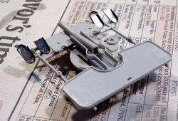
The 20mm Oerlilon cannon is even easier to assemble but I dry-fit the tripod legs of the pintle into the baseplate Part 1F before gluing the assembly so there would be no alignment problems later.
Steps 22 & 23 - This is where we start installing the previous subassemblies onto the deck of the PT boat. While I have dry-fit everything and had to enlarge a few of the holes in the deck to match the pin diameters of a few of the gun mount base plates, everything looks fine. I am going to delay the final installation of these parts until the very end.
In these steps, you also assemble the safety frames around the two 50 caliber mounts. The aft frame as a canvas skirt on the frame to shield the gunner from the bow spray while the forward mount doesn't have the skirt installed in this kit. If the boat you're modeling had the skirts installed fore and aft, you can replicate the skirt with aluminum or lead foil. Removing the molded on skirt from the aft mount frame would be a bit more challenging. On my build, I'm leaving well enough alone. I used liquid cement to assemble the fore and aft frames. The skirts on the aft frame provide more gluing surface for a more solid assembly. The forward frame is sturdy enough after the liquid cement has been allowed to dry.
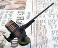
Step 24 - Time for the 40mm Bofors mount and gun. Here is where I start using the Eduard photo-etch. The operators' footpedals are provided by Eduard, so I do the origami and bend them into shape. Attach them to frame 14F and they look pretty good. I assemble the Bofors per the kit instructions and opt for the aluminum barrel, then add some of the Eduard photo-etch to the gun to provide more surface detail.
Step 25 - Eduard provides detailed 40mm ammo racks for backstop part 12D. I've started the origami process to get these racks installed and we're very close to getting this done!
Looking back at the start of this project, I realize with some shock that this build has been going on for a year! That does include some long breaks due to travel and other challenges, but clearly it is time to get this project moving again! While we're getting close to finishing the various subassemblies in the instructions, one fundamental step has yet to be done that is causing increasing problems - the deck is not yet mounted to the hull. I've been holding off on this step as I need the hull open to mount it properly to its display base. This doesn't sound so difficult except I still have to create that display base.
Here is the article describing the construction of PT-596's display base.
Insert time lapse here...
I'm not sure what sequence of events led to the PT 596 being shelved, but it did sit on the shelf for almost five years after completing the pier and water base. The first step was to blow 40psi through the airbrush and clear the layers of dust off the model and base. I had not glued the deck to the hull yet, so I carefully removed the deck and set it aside. I used a lint free cloth to wipe down the hull, water surface and pier, then used a wet cloth to perform the final wipe-down. Numerous years (layers) of dust are now gone.
After removing the machine gun turrets and a few other items from the deck section, I repeated the process above and swabbed the deck of all that dust as well. A few minor details will need to be repaired and a new coat of paint will be applied before we move forward. One thing that I was not pleased with were the feathered paint edges on the camouflage when the full-scale boat had hard-edged paint demarcation lines. The first order of business will be to harden the lines apply a few other touches.
The first long-overdue step applies to the pier. At the end of my scratch-build of the pier, I had applied a homemade wash to the pier which looked good then but had faded over time. It was time to weather that surface again. I used AK Interactive wood wash on all of the wood surfaces of the pier and let it dry. Here is a shot of the pier, still slightly wet, with the newly cleaned deck back on the hull to show off it's green (not dust-colored) surface.
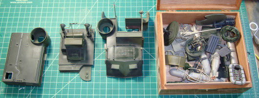
I was strategizing on how to proceed with getting this model finished. As I looked around the deck which was still removable, the deck surface would bow a little and the brittle glue would let loose. Soon I had the deck houses off the deck surface and various other subassemblies all gathered together.
With the model stripped down again, I had acquired some replacement parts to fix a few small items that had been damaged and before we resume assembly, its time to repaint the model and make the camouflage color demarkation lines hard instead of feathered as before. What is going to save lots of time will be the weapons subassemblies that are already painted and weathered. They can go right into place once the foundation is back up to specification.
While I have the deck section going through repair and repaint, I also need to finish some details with the dock as well. I had originally thought about posing the boat in the process of tying up pierside but now I'm going to show the model already tied to the pier and getting resupplied before its next mission. I need to get tired hung over the pier pylons to act as bumpers and get cleats on the pier to tie up the boat. The deck surface is several millimeters below the pier deck so a small gang plank will look good as crates and ammo cans are placed on deck and pierside. Lots of little tasks to do before we see that deck back on the hull again!
As I round up the paints to start the camouflage touch-ups, I realize that I had selected these colors before we had our digital color-matching system running and before new colors from several companies had been released. I ran the US Navy colors for Measure 31/20L through the system and was a bit surprised with the results. I've updated the color chart at the beginning with the new colors that I'll be using with this rebuild.
To be continued...
