Modifying the Italeri 1/48 F-22A Raptor Build Review
By Michael Benolkin
| Date of Review | March 2007 | Manufacturer | Italeri |
|---|---|---|---|
| Subject | Lockheed Martin F-22A Raptor | Scale | 1/48 |
| Kit Number | 0850 | Primary Media | Styrene |
| Pros | Easy build | Cons | Fit of intakes, sparse cockpit, nose angle |
| Skill Level | Basic | MSRP (USD) | $34.95 |
Background
For a brief history of the F-22, look here.
The Kit
The only kit of the Raptor produced to date in 1/48 scale is Italeri's F-22 kit. I built this kit after it was first released nearly seven years ago and it went together reasonably well. You can see this early build-review here. So why are we here again?
The kit, straight out of the box has an interesting issue - while Italeri captured the basic shape and details of the Raptor rather nicely, they missed one rather significant aspect of the design.
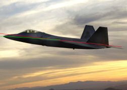
If you draw a line from the tip of the radome to the tip of the stinger between the engine nozzles, this represents the aircraft centerline. While this is correct for the top view of the Raptor design, this is not the case for the side view and this is where Italeri kit deviated from the plan. Take a look:
The side profile shows the red line running through the centerline and indeed the tip of the nose and the stinger are on the line on the Italeri kit. The plan view photo in the lower left shows that same red line and a green line where the nose should slope. The F-22 photo in the lower right shows the same lines to illustrate where the nose is on the real Raptor and where the Italeri nose should be. Because of this glitch in the kit design, the intakes wind up being too large and the underside of the nose sweeps up too much.
The problem lies in how to correct this. Leave it to a Russian to come up with the solution. Noted kit designer Dimitri Malkov not only spotted the problem, but he had also found the solution. With the help of his photo notes, I decided to give this conversion/correction a whirl and share the techniques with you as well. If we're going to all of the trouble to fix the nose, we're definitely going to update that cockpit and add some operational markings to the completed model. My parts list for this project was rather simple and inexpensive:
Parts List
- 0850 Italeri 1/48 F-22A Raptor
- 48002 Golden Dragon 1/48 F-22A Raptor Cockpit
- 48311 Eduard 1/48 F-22 Raptor Detail Set
Construction
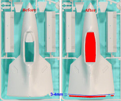
Violating a time-honored tradition of aircraft kit building, work does not start in the cockpit. The first step is to apply Dimitri's corrections to the airframe. In the photo to the right, we have a before and after shot of what we do first. Remove the mating tab at the rear of the upper nose half Part 8A (shaded red) and remove any remnants of it on the underside of the part as well. While you're at it, remove the step around the opening of the cockpit as well as the top of the instrument panel (also in red). Do not remove the canopy sill (the flat edge around the cockpit opening), just the step edge inside of it.
Note the blue line, we're going to mark a spot about 6mm rear edge of the upper nose half on both sides. We're going cut a slight arc from the 3-4mm point back to the rear edge of the upper nose half right at the centerline, then arc back out to the 3-4mm mark on the other side. Make sure the edge you just cut is smooth. Note: This is where Dimitri and I diverged - he made the cut at 0.6mm and I cut this model at 6mm. The results below look good, but comparing my completed fuselage to the real aircraft at the end of this article, I think that 6mm might be a bit too much, so I recommend 3-4mm. You be the judge and adjust accordingly in your build.
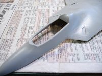
Here is where the magic begins - you're going to glue the tailored Part 8A to the upper fuselage half Part 9B. Do not use cyano for this join. You'll want to use liquid cement (I used Tamiya Extra Thin) and simply press the two parts together. If you're patient and watchful, you can periodically adjust the parts to ensure that the upper surface does not have a step or gap. It took about 10 minutes for the halves to solidify, though the join is still fragile. I used a strip of Evergreen styrene to reinforce the joint, again using liquid cement, and again being watchful over the exterior seam as the liquid cement could soften up your joint. The result is a nose that angles down properly. Now it is time to make the rest of the airframe compatible with our new nose.
You can also see at this point that the opening for the cockpit is now clear of that molded-in step and the original instrument panel coming. This makes room for the new resin tub which we'll get to shortly.
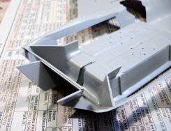
Next is the lower main fuselage half Part 18C. Using the alignment pins at the wingtips to align the upper and lower fuselages, you can see how the intake area needs to be adjusted for the new nose. In the image to the right, you can see how I've cut down the intake trunk to the new line. The blue arrow shows the starting point for the alteration which is at the wing root, the same point we made our alterations on the upper half. This is where the old rule "trim a little, fit a little" really comes to play as you don't want to make any radical changes without periodically checking the fit of the fuselage halves.
Once you get the slope set on both sides of the lower fuselage where the upper fuselage sets almost gap-free atop the lower, it is time to install the intake ducting. Install the kit intakes to the front of the lower fuselage half per the instructions and add the interior intake ducts at the same time. Once again, use that liquid cement and manipulate the intakes as they set up on the front of the lower fuselage half to get a good alignment and no step particularly on the underside. These parts didn't fit that well on the first build, but I was able to get less of a gap problem this time. I still used a bit of Mr. Dissolved Putty to blend the intakes into the lower fuselage, but this was minimal.
Now we're going to do some duct work. I used Mr Dissolved Putty to blend the intake ducts into the intakes and remove any gaps visible when peeking down the intakes. It took a few sessions of putty and wet sanding to get some reasonable intakes. The photo above left shows the intakes prior to putty.
To move things along, I installed the missile bays (Parts 20A/21A) and the main wheel wells (Parts 22A/23A) at this point.
The one area that mystified me the first time I built the kit was the proper placement of the F119 engine thrust vectoring petals (Parts 14C). This time I had good photos to work with and indeed the outer clamshells molded into the rear fuselage halves are integral to the inner surfaces (Parts 14C), but when you install these in the kit, the rear of the petals choke off the engine turbine faces from view. I decided not to worry about it as I had the nice photo-etched surfaces for the petals from the Eduard detail set and they looked good back there.
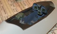
Now that the rear fuselage halves are ready, it is time to get back to that cockpit. The Golden Dragon cockpit isn't bad though there are a few minor problems. The ejection seat is a nice representation of the ACES II seat though it literally disintegrated while I was looking at it. After a half-second of panic, I simply robbed one of my F-16C kits of its Black Box ACES II seat and we were back in business. For some reason, the mold maker decided to replicate a box on the floor of the cockpit tub that would go under the ejection seat. Since neither the original nor the Black Box seat would sit atop the box, I pulled out my Mission Models Microchisel and removed the box from the floor. The cockpit set comes with the cockpit tub, the ejection seat, a nice side stick controller, throttle, and replacement instrument panel cluster. The set was also supposed to have rudder pedals, but these had evidently self-destructed prior to reaching me, but that's okay - the Eduard set also has nice photo-etched rudder pedals.
The cockpit interior of the Raptor is black. I took a little poetic license in my cockpit and painted the tub RLM 66, the side consoles and instrument cluster NATO Black, the O2 hose Olive Drab, and the storage bag on the left rear side of the cockpit a few shades of dark green. I left the photo-etched rudder pedals bare metal. The photo to the right gives the illusion of greater contrast between the RLM 66 and the NATO Black, but that is due to the camera's flash. Without the flash, that cockpit is DARK! I painted the screens of the multi-function displays (MFDs) dark green and added a few drops of Future to the surfaces to make these glass displays look more like glass. The buttons around each of the MFDs was dry-brushed gray. The ejection seat, control stick and throttle were left off until the final steps.
The instrument cluster slides perfectly into the front of the cockpit opening on the upper fuselage. It wedged into place and after a few tweaks to get it 'just right', I bonded it into place with cyano. The cockpit tub went into place next and it too fit nicely. Cyano was once again applied and we now have a nice front office for the Raptor.
 While I was studying the various photos of the Raptor, it was clear that the canopy frame had an interior structure around the base that mounts the various hand-holds and that distinctive gray pressurization seal. Then there is that very noticeable white canopy defogging manifold at the very front of the canopy frame between the inner and outer frames.
With the help of some Evergreen styrene strips, I replicated the canopy interior frame inside the kit part. The handles and manifold will get added later.
With the cockpit set in place, it was time to modify the lower nose half Part 33A to work with our new sloped nose.
The image to the left shows the stock kit part and the modifications that will be needed to make this part work. The area shaded red needs to be removed. I used a cutting wheel in my Dremel tool to make the alteration. The area in blue shows the ares that will need to be removed from the sides of the remaining intake spacer.
If you look at the image to the right, the intakes create a V-shaped cradle between the intakes where the lower nose will sit. If you dry-fit the lower nose (Part 33A) into the V, you'll see how the removed material does change the angle that the nose will sit, but at this new angle, it sits too high in that cradle. Before you start removing the blue area, we need to finish assembling the nose.
Glue 33A to the upper fuselage assembly. Add the intake fillet fairings Parts 31A/32A and let this get set up nice and solid. When you dry-fit the upper and lower fuselage halves, you're going to have to different fit problems at the same time. First will be the need to remove that blue area a little at a time until the nose comes all the way down into the cradle where it belongs. The other will be the sharp upward angle of the top of the intake splitter plates (see image to the left). The top of these splitter plates hit Parts 31A/32A and will need to be carefully trimmed so that they will fit snugly against 31A/32A. I trimmed these WAY too early and wound up with a gap between the top of one splitter plate and 32A. A strip of Evergreen patched the problem and everything fits. Take your time and all will come together nicely.
After eyeballing the fit of the upper and lower assemblies, I happened to peer down the intakes of the inverted model and noticed that the intake trunks are wide open behind Parts 31A/32A at that angle. I used sheet styrene to close this up and even added a visual block at the end of the duct should you manage to get into that angle.
I haven't discussed the installation of other details like the gun doors, etc., but those are adequately covered by the instructions. Granted we've jumped all over the place compared to the instructions, but if you keep an eye on where everything goes, you won't have any problems. Note that gun door 92D will no longer fit since we've shortened that opening with the first surgery, but a quick trim with my sprue cutters rendered a nice fitting door again.
With the major airframe modifications completed, it is now time to marry up the upper and lower fuselage halves. I did this a section at a time with liquid cement and verfied that nothing had gone awry before moving on to the next section. Once the airframe was solidly together, I used Mr. Dissolved Putty to take care of a few minor gaps. Most of these were associated with the rear fairings parts 15D, 16D and 17D. The instructions would have you put these on before mating the top and bottom halves, but I waited until afterwards and removed the alignment pins as well. Even with the pins gone and the parts butt-fitted against the lower fuselage, there were still gaps. Mr. Dissolved Putty took care of that quickly.


