Tamiya 1/32 F4U-1A Corsair Build Review
By Michael Benolkin
| Date of Review | August 2021 | Manufacturer | Tamiya |
|---|---|---|---|
| Subject | F4U-1A Corsair | Scale | 1/32 |
| Kit Number | 60325 | Primary Media | Styrene, Photo-Etch |
| Pros | Beautiful detals | Cons | See text |
| Skill Level | Experienced | MSRP (USD) | $213.00 |
Build Review
For a number of years, I've had Tamiya's 1/32 F4U-1A Corsair kit in my collection as well as on my bucket list. During that time, I've accumulated several aftermarket resin detail sets which looked impressive in their own right, but they didn't inspire the project onto my bench. It wasn't until several new items came together that brought this project to the forefront. First, Quinta Studio produced a cockpit set, fundekals produced a decal set, and 1ManArmy produced a stencil mask set, all for this kit. When these three products arrived, it was time to get to work. I want to build one of the aircraft flown by Major Greg 'Pappy' Boyington, USMC, when he commanded VMF-214. One of his regular mounts was BuNo 17883, but Larry Horyna built this aircraft in his article from six years ago. Instead, I'm thinking about doing the aircraft that was specially marked for a Boyington press event, number 86 'Lucybelle'. Many will remember this aircraft as Lulubelle as that version appeared in the TV series "Black Sheep Squadron', and there's an interesting story about the name's history here.
Aftermarket Parts List:
- Quinta Studio F4U-1A cockpit detail set (QD32040)
- Anyz braided wire (AN021)
- 1ManArmy F4U-1A paint mask (32DET005)
- fundekals 1/32 F4U Corsairs USMC (FD32002)
So with lots of good coverage about building this kit published previously 'out there', I'll focus on the additional products as well as any challenges I encountered. As I gave this kit a serious once-over, I realized that the resin interior sets didn't really add much to the kit. We'll see how the other sets fare as we continue the build. First, I primed the aircraft interior (fuselage, wings, details) Stynylrez black. Stynylrez is the best primer I've ever used (it is also sold as Mig One Shot primer), but it would periodically clog up my airbrush. I typically use double-action airbrushes with different sized needles to support paints of different viscosities, and Stynylrez works fine straight out of the bottle with the 3mm needle. What makes Stynylrez so great is how it will dry almost bulletproof on many different surfaces, but this includes airbrushes. For me, the solution for applying Stynylrez was to change airbrushes. I now have the Iwata HP-M2 single-action airbrush which is ideal for products like Stynylrez and is much easier to clear/clean when a blockage does occur. When cleaning the airbrush after Stynylrez, I found that Windex (w/ammonia) does the best job.
Tamiya recommends that the interior surfaces of the aircraft are chromate green, though some photos show chromate yellow visible in some areas of the airframe. None of the usual modeling references are of any help as most provide color photos of restored warbirds. I ran into the same problem with the Airfix 1/24 F6F-5 as they too claim the interior of the aircraft was chromate green, but Ginter's book on the Hellcat as well as a Grumman color film from World War II (available on YouTube) show that light gray was used instead of chromate green on the production line and the chromate green would appear when an aircraft went into extended depot maintenance. Unfortunately, Steve Ginter hasn't published a title on the F4U/FG-1 series and there isn't an equivalent color film from Vought. For this build, I'll (more or less) follow Tamiya's recommendations. I grabbed the HP-M2 and Mission Models Chromate Green and painted over the primer on many of the parts that aren't supposed to be black.
Instead of using the resin cockpit set or even detail painting the kit cockpit, I'm going to use the interior 'decal' set from Quinta Studio. This is my second project using this system and I learned some good information during this phase. My first project using this system was on Zvezda's 1/48 Mi-24V interior which had no surface details molded onto the instrument panels/side consoles. In that example, the details simply went down over the interior paint using Tamiya Gloss Clear as the laminate coating. The folks at Quinta Studio later suggested using thin cyano which turns out to be a better method once the parts are all in position. More on this later.


The first step was to identify all of the kit parts that will receive Quinta parts and to carefully remove the molded-on details. Quinta's excellent instructions provide the kit's part numbers to make this task easier. I used my Sujuburido planing file to make each surface smooth, then painted them Tamiya NATO Black. When the parts were ready, I applied the decals, or rather, resin parts. To be clear, these aren't really decals. There is no clear carrier film and not much of any adhesive, so the parts won't really stay in place without some help. As recommended by Quinita Studio, I cut the decal sheet to remove the parts I needed for any given step and put it into the water. Like a decal, the resin-printed parts come off the carrier sheet, but unlike a decal, I place the parts onto a paper towel to dry.
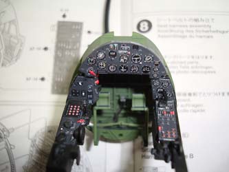
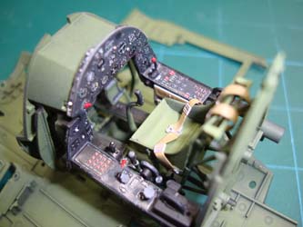
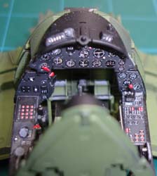
Following the kit's instructions, I built up the front portion of the cockpit making certain I was happy with the airbrushed colors before getting started with the Quinta Studio parts. I did make the mistake of adding some of the smaller detail parts to the side consoles like the trim wheels on the left side and the radiator levers on the right side before applying the Quinta parts. I started with the left side console and noted that the holes in the Quinta left side console part had holes for the trim wheel parts (no carrier film, so no trimming required). I used Future this time as my clear gloss and used this to get the part laminated to the console. The holes were almost large enough to go over the trim wheels, but with some coaxing, I was able to get the part over the trim wheels without harming the resin-printed part and it fit perfectly. I was able to remove the radiator levers and laid down the right console resin-printed part onto a coat of Future. This process was repeated for the main instrument panel and the lower sub-panels. Once the Future had dried and I was happy with the positioning of the parts, I used my tweezers to pull up a corner of each part and apply thin cyano to fix the parts into permanent place.
Next, I built up the rear cockpit bulkhead, seat mount, and pilot's seat. The kit provides photo-etched steel pilot restraints, but I used the Quinta Studio parts instead. This time I placed each strap using the thin cyano, but of course there were shiny spots on the seat where the thin cyano ran out from under the parts. This was easily corrected by lightly spraying Gunze Aqueous Flat Clear and all looks great now.
The keys to completing this cockpit is patience and attention to detail. Before adding a part to the cockpit assembly, you need to ensure that there isn't a Quinta part that needs to be installed first, as some can't be added later as I almost experienced above. At this point, the front and rear portions of the cockpit are dry-fitted together and sitting atop of the lower wing/fuselage for these photos. I still have some small parts to add to the cockpit subassembly as well as the various control boxes that mount to either fuselage half that also have corresponding Quinto Studio faces. The details on the Quinta Studio parts is so clear, you can even tell the time (13:44 local time).
Before I can complete the cockpit, I need to add the throttle quadrant to the left fuselage half and the switch panels on the right, but first I need to change up the primer in the rear fuselage, so I apply Mission Models Yellow Chromate. Next time, I'll use Tamiya's Yellow Green for Chromate Yellow.
You can see the completed throttle quadrant and switch panels in their respective places, all with the remaining Quinta Studio parts applied
Here's what the completed cockpit looks like with the fuselage side details before I glue the fuselage together (finally!).
The fuselage goes together without any problems or gaps. Part of the engine exhaust manifold mounts to the firewall to be aligned later in the assembly process.
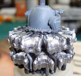
It is time to build up that R-2800 Twin Wasp. I assembled the primed engine bank halves and then applied aluminum to each bank. The gearbox and magnetos are given the light gray called out by the instructions. Out of the box, the engine is nicely detailed, but it lacks ignition wiring. Without getting carried away on details that won't be seen after the model is finished, I wired up the front of the forward bank of cylinders. I used Anyz AN021 coated wire and a pin vise with a #80 drill bit to open holes in the cylinder heads and ignition ring. #80 (0.0135") fits the AN021 wire perfectly.
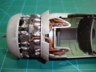
At this point, the instructions have you build up nine 'Y' assemblies that are the intake manifold and exhaust manifold connections to the front bank of cylinders. These are supposed to be glued into place before adding the remaining details to the rear bank of cylinders. I'm already apprehensive about alignment issues between the completed engine assembly and those exhaust manifold pipes installed on the fuselage firewall. I am not interested in another potential fit problem, but the solution is easy enough. I dry-fit each of the nine 'Y' assemblies to the rear of the front bank of cylinders, then dry-fit the rear bank into place. Make any adjustments, as needed, and then dry-fit the induction manifold to the rear of the engine. Each of the pipes on the induction manifold connect up to the inboard portion of the 'Y' assemblies. A few more adjustments, and everything aligns nicely. I applied glue to each 'Y' where it connects to the rear of the front bank of cylinders and set aside the assembly to dry. After an hour, the glue is set up and the induction manifold and rear bank of cylinders can be removed.
As you know heated steel will rust, and steel exposed to salt air (islands and aircraft carriers) will rust, so the F4U had some rusty exhaust plumbing. The problem for me was that I didn't have a bottle of rust-colored paint handy. Back in the days of Rust-All, I'd paint the plumbing dark gray or black, and then go through the four-step Rust-All process for nice results. I know there are some specialty products on the market for convincing rust, but I didn't have these handy either. Instead, I found some old rust-colored pigment powder that had been in my drawer for more than a decade and mixed it with Future. I dabbed the mixture onto the hot parts of the 'Y' assemblies as well as the exhaust ducts on the firewall. Given that this was a mixture using Future, you'd expect the results to be shiny rust (an oxymoron), but the finish is satin in this photo. When you see this next time, it will be treated with a gray oil wash which will not only age the look of the rust, it will also make the appearance dead flat as well. Improvise, adapt, overcome.
The instructions and I temporarily parted ways at this point. In step 29, after assembling both banks of cylinders together, you add those airflow guides around the outside of the cylinders to ensure an even flow of cooling air through the rear bank of cylinders. These are parts K13 and K16. When I tried to install the guides around the engine, alternating between K13 and K16 as shown, I couldn't get anything to fit. The more I tried, the more I got frustrated and I chose to walk away for a while. I came back a few days later, I noticed in the second image part G12 that goes on the bottom of the engine. I installed that first, and then the rest of the parts fit into place around the rest of the engine. If only Tamiya had led off this assembly with that one part in the instructions. Note that once these guides are in place, the cowl flaps are installed and there are two configurations offered. I opted for the cowl flaps that don't open on top of the engine as photos of my subject concur with option C in the instructions.
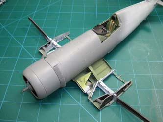
Here's the engine mounted to the front of the fuselage assembly. When I dry-fitted the engine earlier, I was correct about getting all of that exhaust plumbing aligned with their corresponding pipes on the engine assembly. The good news is that the alignment wasn't far off, but after verifying that the engine would align with some tweaking of several pipes, I glued the engine assembly to the firewall and then held the two assemblies together for several minutes while the glue dried.
The next section deals with the horizontal stabilizers and elevators. You have the option of posing the elevators in the drooped or neutral positions. You'll note that the kit accurately portrays the horizontal stabs/elevators - Vought only designed one stab and elevator, then flipped it upside down for the other side of the aircraft. If you choose to droop your elevators, make sure that you droop one down and the other up so that when they're installed, they're both drooping in the same direction.
The last step before moving on to the wings is the tailwheel assembly. Tamiya gives you two choices of tailwheel fork, two choices of tail cone configuration, and the option to leave off the tailhook, all depending on which of the three subjects you're building. I'm doing the USMC configuration (option C), so I follow the steps accordingly. Here's the tailwheel mount without the fork installed as I need to get it reprimed and painted before installation in the tail. This is quite different from other models where you stick the tailwheel fork into a hole on the underside of the tail and call it a day.
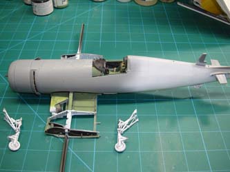
After building up the tailwheel assembly above, I opted to jump ahead 13 steps and build the main gear struts. The strut on the left has been assembled with the steel rod insert, the strut on the right is assembled the same way, but a variety of other parts are added to provide oleo forks, retraction arms, brake housing, and hydraulic lines. The rack on the front for the upper gear door and the main wheel assembly will get installed after paint. Now that this photo for the contrast in detail is done, I've got to add the same details to that bare strut on the left.
The landing gear is assembled and painted. These are easily the most complicated landing gear assemblies I can remember building - not difficult, but time and patience is required.
The tailwheel strut assembly is installed in the tail cone, the tailwheel fork and tailwheel will be added later.
Construction of the wing mid-section is underway and I'm doing a little test-fitting with the fuselage to understand how everything is going to fit together.
The wing mid-section goes together smoothly until we get to the flap pushrods. I'm building my Corsair with the flaps extended, so once the wing mid-section is nearly competed, Step 51 is where you make the flap positioning decision and select the corresponding pushrods that install between the mid-section and outer wing section. The inboard pushrods have pins that mount to holes just behind the main spar and just before the wing trailing edge. The problem here is that there are no holes in the wing trailing edge, but if you were paying attention in Step 44, you open up holes in parts N37 and N38 to create those holes. Guess who missed that step? The instructions get me again. The trailing edge pins on the inboard pushrods were removed and the modified pushrods were installed. The wing bulkheads N39 and N40 were mounted over the pushrods and the outboard pushrods mount normally.
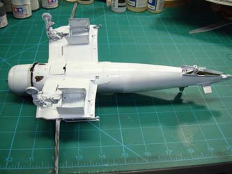
The fit of the wing center section and the fuselage is gap-free, just like most of the rest of this model. In these photos, the landing gear is not really installed yet, just dry-fitted so the stance looks wrong for now...
The landing gear struts are now glued into place and the gear doors are mounted. If there is one thing I dislike more than assembling poor-fitting individual track links, it is hanging gear doors. These doors are well designed by Tamiya and were a joy to work with!
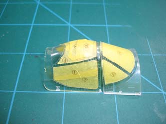
The kit comes with yellow tape masks with the outlines printed on the tape where you can cut the masks with your trusty X-Acto knife and place then according to the instructions. I also have a set of yellow tape dye-cut paint masks from Eduard, so I used the Tamiya masks on the outside of the canopy and windscreen while using the Eduard masks to protect the insides.
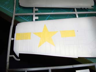
The 1ManArmy paint masks are also yellow tape and dye cut, though their process provides much sharper/more precise cuts. There are two types of masks provided in each set:
- masks that are applied over a pre-painted surface for letters, numbers, stenciling, or simple national markings
- multi-part masks which replicate a multi-color national marking or insignia
The first type of mask is simple enough, lay the rectangular mask over the location for the stencil, airbrush carefully through the stencil, and remove the mask. The second type is a little more challenging. When I built the Kinetic 1/24 P-47D (look here), I used paint masks there for the national markings and had challenges aligning the different masks for each color, but the Montex masks are dye-cut vinyl, so they can be carefully repositioned. These masks are yellow-tape and require assistance to place them onto the model. The instructions recommend transfer film which is readily available in the crafts section of your store or online. I ordered some medium tack transfer film from Amazon, then cut pieces large enough to move each mask. The medium tack transfer paper can lay directly on the mask sheet and won't pull up the yellow tape masks. To use the transfer paper, use a burnishing tool to rub the transfer paper onto the part(s) of the mask you'd like to relocate. Carefully lift the transfer paper to ensure you have the right mask parts adhering to the paper.
I apply a coat of Tamiya Gloss White thinned with lacquer thinner. Thinning Tamiya acrylics with lacquer thinner does two things, first of course, it thins the mixture for smoother flow onto the model surface; and second, the lacquer thinner causes the paint to dry/cure much faster, so the wait time is drastically reduced. Verify where you want to apply the mask and carefully lay the transfer paper onto the model's surface. The adhesive on the mask is much stronger than the transfer paper, so the masks go on smoothly. If you make a mistake however, you'll need another mask set as there may not be spares provided for a given mask.
With the white areas of the stars and bars masked, I applied the insignia blue. One error I made on the P-47 was that I didn't spray the blue across a large enough area, so the blue wasn't uniform in coverage.
Now here is where I got into trouble with these masks. I pull the next masks that go over the blue on the transfer paper, but it was difficult aligning the mask to go over the white background mask. The first masks and backgrounds are both insignia blue, and despite all of the lighting on my bench, I couldn't see through the transfer film well enough to align these next masks. This isn't a design flaw with the 1ManArmy masks, it is my inexperience with this type of mask. The next time around, I'll paint the white background, apply the star and bars mask, paint the blue in a much larger area, then using a contrasting colored marker like silver, I'll apply dots on the corners or points on each mask so alignment is much easier to see.
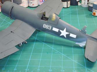
With the masks removed, you can see that the wing's national marking didn't look too bad, but I couldn't even align the blue background masks on the fuselage sides. Still, you can see how sharp those markings are in just one color. The 883 side-numbers came out looking great, but the national markings on the wings and fuselage sides will be repainted and decals will be used instead.
A note about the colors and paint layers used - Since I was going to attempt to not use decals in this build, I primed the model with black Stynylrez (as mentioned previously, the a coat of Tamiya Gloss White where the national and ID markings would be applied. Next came the Insignia Blue, which was a mixture of Tamiya Blue and Sea Blue, applied over the mask areas, followed by NATO Black painted where the walkway stripes and walkways would be. After realizing the national markings masks were not going to work, those were removed and all of the upper surfaces would receive the base coat of 'Sea Blue'. What comes out of most paint bottles is much darker than what you see here and looking at period photos, the Sea Blue did fade in the sun and salt air. I mixed a bit of Tamiya Neutral Gray with their Sea Blue to get the shade I liked. I made enough of that mixture to keep in a spare bottle so I could match later touch-ups. The underside of the fuselage/inner wing sections received Tamiya White, and being that this is a tri-color scheme, the third color is supposed to be Intermediate Blue. Tamiya's Intermediate Blue was too dark, so I made a mixture of Tamiya Intermediate Blue with Tamiya White, and applied that to the vertical stab and the undersides of the outer wing sections.
For my next challenge, I needed to replace the national markings. I thought about the kit's decals, and then looked at the decal set for the F4U by fundekals. The fundekal set covers a variety of aircraft including 883 at three different points of time and serving VMF-223, VMF-214, and finally VMF-215. I opted for the timeframe 883 was with VMF-214 and as one of the aircraft flown by its commanding officer, Major Gregory 'Pappy' Boyington. While Tamiya provided 'standard' national insignia with the kit, the folks at fundekals have done intensive research and found some unique surrounds applied to the insignia. You can see the story for yourself here. This also brought out several other things of note: the 1ManArmy stencils are basically copies of the kit's decals rendered as masks, so beyond the maintenance stencil placement, there are no instructions for the specific subject masks included in the set (you use the kit's instructions); the Tamiya decals have a band of clear carrier film around each decal and the decals themselves are relatively thick. I recall using Tamiya's decals on their 1/48 F4D Skyray kit years ago and the decals were unresponsive to MicroSet and MicroSol. I used stronger products up to SolvaSet, and I thought I heard those decals laughing at me. The fundekals decals (printed by Cartograf) have no clear surround, the edges of the decal are color and they are thinner. You can see here how nicely they went on the model.
The last thing I wanted out of this project was a clean Corsair. I was inspired by a color photo of an F4U aboard an aircraft carrier and the amount of dust/dirt/grit in the panel lines and rivets. The photo is on the back cover of Classic Warship's F4U-1 Corsair Volume 2. It was time to get to work. I applied a clear gloss coat over the model using Tamiya Clear thinned with lacquer thinner, which provides a protective coat over the paint and decals underneath. Oil-based washes won't attack acrylic if you don't over-work them, so I mixed up a tan wash and applied it to the panel lines and rivet lines of the horizontal stabs. I grabbed a roll of shop towels (the blue paper towels that don't leave lint/debris behind like kitchen paper towels) and rubbed off the excess wash. Where there were any stubborn spots, a Q-Tip dipped in mineral spirits, tapped against a shop towel to make the Q-Tip damp, not wet, and rub off the stubborn spots. When I was satisfied, I did this same process to the fuselage.
Before I weathered the wings, I wanted to try out the stencil masks provided by 1ManArmy's set which you can see here after airbrushing white through them. To keep overspray off the model, I had cut a rectangle out of a scrap of paper and used it as a mask for each stencil. Once the painted stencils had dried, I resumed washing the wings. Remember that sections of the outer wing panels and flight control surfaces a fabric-covered and not metal, so those rib details shouldn't be washed like panel lines.
The process of weathering continues under the aircraft, though for contrast, I changed over to a dark gray wash. To wrap things up, I used light streaks of NATO Black over the wings for gun gas as well as the shell ejector ports under the wings, and the exhaust stains. This was all covered with a final coat of Gunze Aqueous Flat Clear over the model, before using an oil streaking product under the centerline where engine oil would drip down the underside of the fuselage. The one thing about radial engines, if you don't see an oil puddle under the aircraft, don't fly it - have the crew chief refill the oil reservoir.
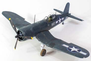
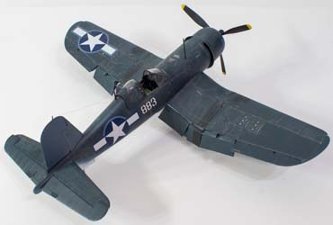
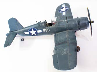
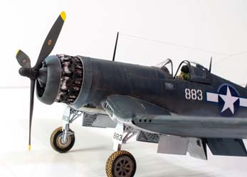
Here's the final result with antennae added, flaps installed, and the masks all removed. I'm rather pleased with the results!
This has been an enjoyable project that requires some patience and attention to detail to complete. The instructions can be a bit of a handful if you don't study them in advance as they are so busy in each diagram that you can go off the path easily. A few times I found myself grabbing the wrong parts a few different times. The instructions start off on a common mission and clearly indicate the unique differences for one of three different subject options (I close the USMC configuration - option C). Then the instructions split off to one of two sections - wings extended or wings folded. In the wings extended section, you have flaps up or flaps down. You get the idea. Just watch the road signs or you might get lost.
