SM 1/72 Canbberra T.4 Kit Build Review
By Michael Gething
| Date of Review | January 2024 | Manufacturer | SM |
|---|---|---|---|
| Subject | Canbberra T.4 | Scale | 1/72 |
| Kit Number | 7239 | Primary Media | Styrene |
| Pros | Excellent surface detail | Cons | No location lugs |
| Skill Level | Experienced | MSRP (GBP) | £20 |
Build Review
First flown on Friday 13 May 1949, the English Electric (later BAC) Canberra was a mainstay of the RAF’s tactical strike force throughout from 1951 to 1972, while the dedicated photo reconnaissance variants continued through to the 21st Century, with the last iteration, the PR.9, finally withdrawn in 2006. It was widely exported around the world and built under licence in Australia and the United States (where, as the B-57 and RB-57, it was further developed). Both Australian and US Canberras saw operational service over Vietnam.
As it happens, your reviewer was born on the day of the Canberra’s maiden flight and was fortunate to fly in the type twice during his journalistic career. This build was a nostalgic event, as I completed the model to depict the aircraft in which I flew in August 1972 – WJ879. The kit was produced by a small-scale UK operation, S&M Models, run by Mel Bromley, who sadly passed away a couple of years ago. The business was closed and, as of this writing, what became of the existing stock is unknown. However, other dealers have advertised some S&M products, so if you wish this particular model, then search the web is my advice.
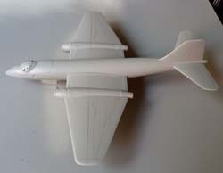
The kit itself comprises 65 parts of injected moulded grey styrene over six frets, plus one transparency fret comprising the front upper fuselage, canopy and the two upper fuselage portholes as a single moulding, plus the side window on the port side. The surface detail is excellent but there are no locating lugs or tabs to aid construction, thus the modeller must treat them as one would a vac-form kit, making guide vanes where necessary.
A clear, simple six-page A5 instruction sheet shows the sprue sets with part numbers identified and the process of assembly. A small word of warning – some parts are small and delicate, so take care when separating from the sprue. Also, as the T.4 is effectively a dual control B.2, the sprues also contain the parts for the B.2 nose and cockpit. There is an A4 four-view colour profile of the aircraft in the red, white and light aircraft grey colours, with markings for WT488/Y of 231 Operational Conversion Unit (OCU) based at RAF Cottesmore in 1973, complete with all the various warning stencils and small markings.
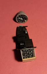
Following the instructions, stages 1 through 9 and 12 through 14 cover the cockpit area and nose wheel bay. Stages 10 and 11 cover the main undercarriage legs and wheels, which I left until after the otherwise completed model was painted and decals applied, while stage 15 was the assembly of the main undercarriage bays which would later be fitted inside the wings. There are bulkheads, instrument panels and twin control columns plus three four-part ejection seats (which although adequate – I used them – other modellers might prefer to acquire after-market resin seats with more detail). While assembling these parts together, it is useful the fit-check them within the two fuselage halves, as a certain amount of fettling was required.
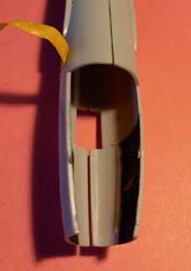
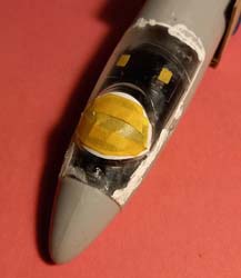
Considering how best to do this, I prepared the main fuselage halves to be joined, adding guides from plastic card to help the fit. I then cemented the fin and rear third of the fuselage together. Once firmly set, it was then possible to gently open the front part of the fuselage to drop in the cockpit assembly.
It is also worth considering the addition of nose weight needed within the fuselage as, in both real life and model form, the Canberra is a natural ‘tail-sitter’. To this end, I created a box structure above the nose wheel bay behind the rear bulkhead and filled with fishing shot secured with PVA glue. I also filled the solid nose (parts 42-43) in a similar manner. [I subsequently discovered an after-market set of nose ballast and undercarriage legs in white metal from SAC, although whether this remains available is uncertain. The ballast takes the form of white metal versions of parts 23 and 28 – the cockpit floor units.]
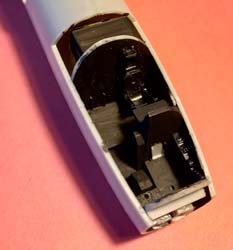
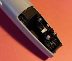
The basic interior of the Canberra is matt black and I picked out the details with some white and light grey dry brushing. Although I created the black/yellow firing handles for the ejection seats from rose wire, sadly the curve and thickness of the main canopy precluded their use. The ejection seats were basically black and, although not supplied, I added three crew figures.
Stage 16 formally brings the two fuselage halves together with the cockpit assembly, the solid nose cone and transparency fuselage/canopy section. I have to admit that despite much filing and fettling the rear end still sat slightly proud, but further filing/sanding managed to bring it down to acceptable levels.
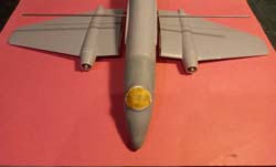
Stage 17 brings the two engine jet pipes and mountings together, while stage 18 addresses the two intake assemblies. Stage 19 covers the wing assembly, first requiring the undercarriage bays from stage 15 to be inserted in the lower wing halves. Then, after joining the upper and lower wing halves together and sanding the joint lines where necessary, the engine exhausts were fitted, which needed a little fettling and then a little filler – I use Perfect Plastic Putty. This stage also brings the wings to the fuselage, but I held off for the moment. Adding the two intake assemblies to the front of the engine nacelles is in stage 20, but I added them here, again needing a little fettling and filling.
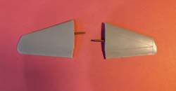
Assembly of the tailplanes and their attachment to the rear fuselage is the main element of stage 20, as was the assembly and fitting of the wing tip tanks. The latter I held off until after painting. At this stage, I painted the interior of the engine intakes and exhausts with Humbrol Gunmetal while pondering fitment of the wings and tailplanes without the traditional locating tabs. (What Sherlock Holmes would have called ‘a three-pipe problem’.) In the end, I decided that what was required for the wings was what the real aircraft had – a main spar crossing the fuselage into both wings.
My solution, which worked well, was to use a steel binding rod from an old magazine binder. I drilled a hole in either side of the fuselage mounting area, slid the rod through and trimmed it to size and slid the wings over it, then cementing at the wing/fuselage joint. This allowed the wings to match and prevent drooping while the cement solidified. A similar approach was used for the tailplanes although, as some dihedral was required, each side required a smaller, separate length of rod … and it worked. So now the model was basically complete, leaving only the wing tip tanks and undercarriage assemblies to attach, after painting and decaling.
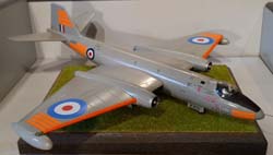
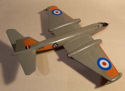
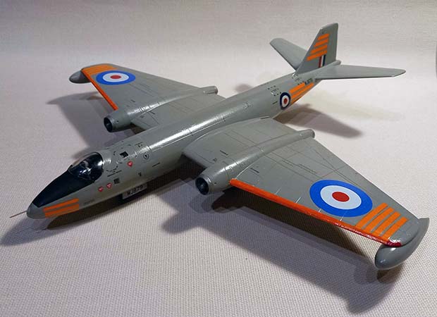
My next conundrum was the exact paint scheme. I was unable to take a photo of the actual aircraft on the day but recalled it was overall silver or light aircraft grey, with orange day-glo panel trimming. Research on the web drew a blank for a photo of my aircraft (WJ879) at the time of my flight – August 1972. However, I came across a four-view colour drawing (from the Airfix 1/48 Canberra kit) of WJ870 of 231 OCU in 1971, resplendent in light aircraft grey with day-glo trim. So, using this as a fair bet, having masked the canopy and two upper fuselage portholes, I sprayed the aircraft with a Tamiya ‘rattle can’ of AS-2 light grey (as close as made no difference). I was then able to mask of the upper nose to paint the anti-glare panel of matt black. As a final detail, I filled the port side fuselage window with Mico Kristal Klear, rather than attempt to fir the proved window transparency.
The model was then coated in a gloss varnish (Klear) ahead of decal application, which took some time with all the stencil details. The decals were drawn from various sources: the kit set, the Matchbox PR.9 kit and the extra day-glo stripes sourced from Xtradecal’s set X72115 (Meteor TT. Mk.8 day-glo orange stripes). The serial numbers were created by a chum in my local IPMS branch (thank you Dave). However, I found difficulty in applying the wing leading day-glo decals (despite liberal coatings of decal softener), so I masked off the areas and brush-painted three coats of white and then three coats of Lifecolor LC23 matt fluorescent orange, which matched the decal shade perfectly. To avoid decal break-up on the remaining day-glo panels, I coated the sheet with Microscale’s Liquid Decal Film, which ensured an easier application.
All that remained was the undercarriage. I pre-painted the various doors (parts 9, 10, 14, 15 and 19) with AS-2 on the outside and Humbrol silver on the inner surfaces and undercarriage bays. Once the doors were painted and given a coat of Klear, the serial numbers for the nose-wheel doors were applied. The legs and supporting struts (very delicate, so take care) were done in silver. All the wheels were two-parters, so these were cemented together and the joint line carefully sanded, then painted (stages 10 and 11), although they were not fitted to the model until stages 21 and 22. I attached the main wheel elements first and left them to solidify overnight, before adding the supporting struts and doors, after which the nose wheel assembly was attached.
The final addition was an 8mm pitot tube (not supplied, so fabricated from a pin) to the nose cone, as per the references. The final challenge was a need to add more nose weight as the balance of the model was marginal. The practical solution was to add some more fishing shot in the nose wheel bay, secured with PVA glue. Although, obviously, not accurate, it is invisible when sat, now firmly nose down, on the base.
While perhaps not a 100% accurate depiction of my aircraft, I’m happy with the result which commemorates a flight some 51 years ago. And for those curious readers, wondering what my other Canberra flight was, I flew in a TT.18 of 7 Sqn from St. Mawgan on 13 May 1976, 26 years to the day after the prototype flew (but that’s another story).
