Roden 1/32 Stearman N2S-3 'Yellow Peril' Kit Build Review
By Michael Benolkin
| Date of Review | June 2020 | Manufacturer | Roden |
|---|---|---|---|
| Subject | Stearman N2S-3 'Yellow Peril' | Scale | 1/32 |
| Kit Number | 0631 | Primary Media | Styrene |
| Pros | Nice details | Cons | See text |
| Skill Level | Experienced | MSRP (USD) | $64.99 |
Build Review
For a look at this kit out of the box and/or a brief summary of this subject's history, look here.
As I mentioned in the in-box look at this kit, this isn't going to be a complex build, but it has the potential to be a beautiful model with a little preparation work. I spent a while doing some research on the Stearman Model 75 series which includes the R-670-powered PT-17/N2S-1/3, R-680-powered PT-13/N2S-2/5, and the R-755 PT-18. All of these variants were essentially the same aircraft with the same performance (all of the engines were rated at 220 horsepower) though some were equipped for instrument training (PT-13C/PT-17A/PT-18A). There are obviously differences in engine details between the R-670, R-680 and R-755, and there are also subtle differences in the different versions of each engine that were used throughout the production run that spanned from 1934 through 1944. For this build, I'm going to stick with the R-670 as depicted in the kit.
One thing I learned during my time as a restoration volunteer at the Pima Air and Space Museum years ago, fabric covered airframes and control surfaces are treated to multiple coats of silver dope for protection/durability before receiving their final colors (if any). The Stearman trainers were no different and even the interior surfaces of the fabric inside the cockpit are also treated with silver dope. Over time, some cockpit interiors are painted in one color or another, but all of the fabric surfaces start in silver dope. Looking at the beautifully restored PT-13 at the National Museum of the United States Air Force, you can see the interior fabric is silver dope, but the aluminum skeleton is gray. Other period photos appear to have silver/gray aluminum skeletons. The tubular framework around the cockpits, along with the foot troughs, appear to be bronze green in the restoration and in other period examples, though others appear to be interior green. I'm going with bronze green in this build.
Exterior colors of the Model 75 do vary by service and function. With pre-war USAAC trainers, they are True Blue fuselages with Orange-Yellow wings/tail surfaces and after the start of the war, they were left in silver dope overall. U.S. Navy examples were generally Orange-Yellow overall (hence the nick-name 'Yellow Peril'), though some that were assigned to fleet units outside of training schools would carry colorful fuselage and tail identification colors. In this build, I was initially going with the pre-war USAAC colors as depicted on the box art but decided to do that subject in the next one (I have two kits). This will be an N2S-3 'Yellow Peril' example.
So with that out of the way, I needed to take care of some logistics. The True Blue (ANA 501) and Orange-Yellow (ANA 506) are not available from very many paint brands, but Hataka has them in acrylic and lacquer, so those were put on order. I also wanted pilot restraints, and while Eduard produces a crap-load of 1/32 seatbelt sets, the ones that came closest to what I wanted was the set designed for the Kitty Hawk 1/32 T-6 Texan. While the kit is still too new (as of this date) for aftermarket items, the instrument panels are not bad out of the box, though I may replace the decal instrument faces with those from Airscale. Decals are also not yet available, but I found several sets of 1/32 USAAC and USN decal sets from Yellow-Wings Decals which will work perfectly for both builds.
My first step was to prime the exterior and interior fabric surfaces with silver dope. For this, I used Tamiya acrylic silver thinned with lacquer thinner and sprayed the majority of the parts using my trusty Iwata airbrush.
Before I could do anything with this sprue tree, I spent some time using a variety of tools to clean/clear mold flash that affected numerous areas on the tree. I didn't have any bronze green handy, so I mixed Tamiya RAF Green acrylic with Tamiya Dark Blue acrylic until I got the right hue, then thinned it with lacquer thinner before applying it via airbrush.
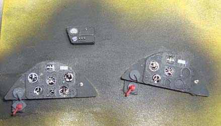
The instrument panels were painted Tamiya NATO Black, and soon I'll begin the process of adding instrument faces. I found a PT-17 pilot's manual from WWII and have the cockpit layouts needed for this build. The photos from the NMUSAF will be handy, but the electric starter and a few other details are post-war modifications that don't apply to this build.
I also primed the interior of the fuselage halves with the Tamiya Silver to replicate that look. I thought briefly about masking and painting the skeleton with a different color for a little contrast like the NMUSAF example, but once the model is built, I don't think it will be very visible.
The first step is to glue the halves of the Continental engine together. This is where test-fitting is essential as you'll quickly find the ejector pin remnants that are in the way. The crankcase is given a coat of engine gray while the cylinder heads receive silver uppers and black lowers. Next will come bolt heads and then adding the ignition, intake and exhaust manifolds, and other details to complete this assembly. Since the wartime Model 75s didn't have cowlings, this engine will be quite visible on the firewall of this build.
Next was the ignition ring - you can see in the image on the left that the spark plug lines are as thick as the ring itself but fits nicely. Instead, I removed the molded-on spark plug wires, drilled out the connecting holes on the ring for not only the front bank of spark plugs, but also the rear bank which is missing from this kit. I also drilled out the spark plugs themselves to receive wire leads, and I was planning on using the finest gauge of wire I have on hand. Then I received Anyz's 0.3mm plastic-coated braided wire (look here) and decided to try it instead. The wire worked nicely as you can see and the front and rear banks of spark plugs are all connected. I used cyano to place each wire into its respective hole.
Here is where Roden's instructions are as good as the fit of these parts (not so good). The diagrams in the instructions show many of the parts go 'somewhere over there', but I worked through it. The push rod assembly mounts to the rear of the engine, but the fit was awful. I wound up trimming each tube to fit under the rocker arm cover and place it with a drop of cyano because liquid cement was not up to this task. This was followed up by the intake manifold and the multi-part exhaust manifold, all of which fitted as well as the pushrod assembly and all of which were also fixed into place with a drop of cyano. I had so much fun during this part of the project that I spend lots of time online trying to find an aftermarket option for the Continental R-675, but none exist anymore. At one time, there was a company called 'Engines n Things' which you could count on one hand the number of radial engines they didn't make, but I guess I missed the memo of their leaving the hobby. At least I have some good insight to what I need to do when I build up the second PT-17.
With the engine finished and set aside, it is time to build up the wings. These fit together nicely. I decided to swap projects and this will be a 'Yellow Peril' (USN) trainer and the second PT-17 will be the pre-war USAAC trainer.
Using Hataka's Orange-Yellow lacquer, I applied the base coat over the silver (dope) primer. The coverage is good but I'll be applying another coat to smooth out the coverage after the fuselage is assembled. In these photos, the fuselage halves are dry-fitted and the alignment on the underside of the fuselage was awful until I removed the locator pin under the front cockpit. Now everything aligns nicely.
The three-piece forward nose section concerned me, but cementing one seam at a time, the pieces align with a little persuasion. As you can see, the engine drops right into place and the nose aligns nicely with the main fuselage. Another step needed was dry-fitting the lower wings into the fuselage as there is some trimming required at the wing roots to get a nice fit. Nothing challenging, but definitely worth taking your time here.
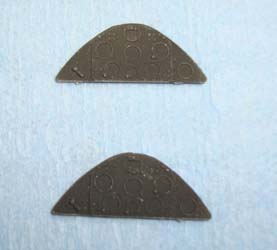
It is time to finish up the interior and while most of the components are painted, I needed to work on the instrument panels. The instructions have you put the same instrument layout on both panels, which may be accurate for the PT-17, but for the N2S-3, the rear panel was minimalist. The image on the left shows the stock panels, while on the right, I've added the fuel selector subpanels below the magneto switches. I replaced the molded-on mag switches with parts from the new Anyz magneto and fuel selector set. These are now ready for installation.
While I was working on the instrument panels, I also pre-painted the various interior parts using the aircraft in the National Museum of the United States Air Force as an example. You can see the Eduard pilot restrains here that work perfectly for this build.
Assembly of the frame is not at all straightforward. There are no pins/locating holes, just butt joints on the tubes. I was not getting anywhere with the Tamiya liquid cement, so I went with the same technique I used with the engine pushrod tubes and exhaust manifold - thin cyano and zip kicker. I tacked a joint or two at a time and repeatedly eyeballed the frame alignment to avoid the inevitable twist or other deformation that sometimes happens if you work too fast. Using this technique, the frame was completely solid in about 30 minutes.
You can see four tube extensions coming out of the rear of the frame, these drop into slots molded into the fuselage halves that aren't big enough for the task. A round file made that adjustment and the frame drops perfectly into the fuselage halves. The firewall extends slightly forward of the fuselage halves as it is used to align that three-piece nose section to the main fuselage. In this dry-fitting, all of the seams close up nicely and it is time the install the instrument panels, backrests, and glue up the fuselage.
With the dry-fitting successful, I glued the fuselage halves together, added the ventral pan between the landing gear legs, and the nose section assembled previously. With paint touch-ups completed, I added the padded edges around the cockpit openings as well as the walkways on the lower wings. After a few more details are addressed, it will be time for decals before mating the wings to the fuselage. I'll point out here that I had pre-drilled holes for the rigging wires as this kit simply has recesses where the wires would go. We'll see soon how close my hole alignment estimates worked out.
The markings were simple on the N2S basic trainers, so I sourced some decals from Yellow-Wings' 1/32 F4B-4 sheet that I've had stashed away for almost 12 years. Given their age, I expected the decals to shatter in the water, but only one roundel cracked in half after placement. These were laid down over a clear coat of Future, then carefully applied Mr Decal Setter and Mr Decal Softer to get the decals to conform to the surface details. This photo was taken while I was still working out a few air bubbles under the decals. Once they were dry, I applied another coat of Future, then a coat Gunze Clear Flat. I didn't mess with the stenciling on this one and the '109' aircraft number used to be 6-F-10 before repurposing.
I pulled out my trusty HobbyZone AJ01 aircraft jig and had to rummage around my shop to find all of the parts. This is the first opportunity I've had to use this on a biplane project, so I had put the upper wing clamps away 'for safe keeping' and further dismantled the jig to use for applying decals. It is all back together and it is time to square everything up and add the various struts.
I squared-up the lower wings and tail feathers and applied Tamiya Extra Thin Cement. When I released the wing clamps on the jig, the model came crashing down. The glue had no effect. While Tamiya cement did work on the unplainted seams, it did exactly the same with the painted subassemblies as it did assembling the engine and interior - nothing. I pulled out some cyano and now have the airframe (less the upper wing and struts) now assembled (finally). I am so ready to wrap this build up and giving the ICM PT-17 kit a go for the next subject. In the meantime, I'm hoping to have this project wrapped up in the next installment.
So much for finishing the model. I set the model back into the jig to add the top wing with the cabane and interplane struts only to find that none of the struts fit. I drilled out all of the holes and tried again, but the lower pins on the cabane struts are not properly molded (almost non-existent) and even with the help of cyano, the upper wing just won't mount. I may replace the bad pins with wire and try again in the future, but for now this beastie is going to the back bench. Out of the box, this kit just isn't buildable.


