
Revell 1/72 Elco PT-155 Kit Build Review
By Dr. Don Alberts, ASM #1
Drawings by Mike Druzolowski
| Date of Review | 1976 | Manufacturer | Revell |
|---|---|---|---|
| Subject | PT-155 (PT-117 Kit) | Scale | 1/72 |
| Kit Number | H310 | Primary Media | Styrene |
| Pros | Easy build out of the box | Cons | Corrections required to achieve accurate model |
| Skill Level | Basic | MSRP (USD) | Out of Production |
Introduction
I saw this PT boat on Don's shelf during an IPMS club function at his house. Anyone who knows Don Alberts also knows that he is one of the "best of the best" modelers within IPMS. I asked him if he'd write up an article on the Revell PT boats, and instead he dug out an IPMS Quarterly - he had already written the article - back in 1976! For those of you that have older back-issues, this article appeared in the IMPS-USA Quarterly, Volume 11 #4, pp 190-195. I have taken his article, almost verbatim, and updated it with current color photographs of the boat. I wonder if my projects will look this good 22 years later?
History
The part played by the US Navy's PT Boats during WWII certainly make these small craft attractive to the military modeler, but several factors have tended to keep PT models out of the collections of serious builders. Selection of plastic kits of these boats is very restricted. Until PT articles appeared in IPMS Update 11U1 and IPMS Quarterly 11Q3, little information was readily available on the boats themselves of on their significant place in WWII naval history.
 |
| Squadron 9 boats loaded on a frieghter for shipment to the South Pacific, November 1942. PT-155 in background, showing radar installation. Photo from Bulkley, At Close Quarters |
Of the two major types of PT Boats used by the US Navy, the 78-foot Higgins and the 80-foot Elco, only the Elco is adequately reproduced in kit form. Revell had a kit of the Higgins boat to approximately 1/100 scale, but it is toy-like and too small for super-detailing. If you really have to have a model of the Higgins boat, this little kit is for you; however, much better plastic kits of the 80-foot Elco boat are available.
The Kit
Of these, I chose Revell's 1/72 scale model instead of the 1/64 scale Lindberg kit. The Lindberg boat is significantly less accurate, and Revell's use of 1/72 offered several advantages. Quality accessories are available in this scale. Useable figures for dioramas are available in HO (1/76) scale. Revell's kit is also to the same scale as the excellent Airfix 73-foot Vosper MTB kit for modelers wishing to reproduce both these light Allied vessels.
With the Revell kit there is some good news and bad news. The general outline and sizes of the hull, deck houses and fittings, cockpit, turrets and torpedo tubes are quite accurate. This makes the project worthwhile. The bad news, and not really that bad, is that most of the fittings and details are crude and toy-like and must be replaced or produced from scratch. Manufacturing and cost considerations account for this lack of sophistication, as does the age of the kit itself. On balance, however, for a reasonable investment of effort, an accurate and detailed model of the Elco boat can be produced from the Revell kit.

The kit represents the early type of 80-foot Elco boat, PT-103 through PT-196. These boats were used mainly in the Pacific and were built from June 1942 to March 1943. I chose PT-155, a Squadron 9 boat, as a subject since it remained fairly 'standard' through mid-1941. My model shows PT-155 in the color scheme and configuration that it carried during the Solomons Campaign for New Georgia, Rendova, and Kolombangara Islands in the spring and early summer of 1943. After that time, major changes were introduced into new PT boat designs, and boats already in the Pacific were extensively modified. Additional armament was universally added, and torpedo tubes were often replaced or augmented by depth charge racks. Deck fittings varied considerably as individual crews changed the 'standard' arrangement to suit their needs.
The Revell kit can be converted into later model boats since basic shapes remained unchanged, but the modeler needs photographic or written evidence of the actual configuration of his/her subject before undertaking such a project. Photographs of some specific PT boats are available from the National Archives' photographic branch, and the books listed in the bibliography contain limited pictures of the boats.
Only a few materials are needed for this super-detailing job. Sheet styrene in .010, .015, .020 and .030-inch thickness. Styrene rod in .75mm, 1mm and 1.25mm diameter. You will also need two pair of 1/72 .50 caliber Browning aircraft machine guns. With these materials and a little patience and time, the Revell kit can be converted into a genuinely desirable replica.
Hull

Little work is needed here. Remove locating pins on the hull upper surface and sand the surface smooth for a good fit to the deck. However, do not assemble the deck to the hull yet. Remove all raised lines on the stern. These represent linkages used to operate the muffler bypass system. After removing he mold lines from the mufflers (kit parts 8 & 9), glue them into the stern recesses. Now using the .75mm rod and .010-inch wire, construct the port and starboard linkages using Figure A and your photos as guides. I used cyano to glue the wire to the plastic rod. Regardless of whether the boat will be displayed in or out of a water setting, do not install the rudders, propellers or drive shafts at this point; they will only be broken and will make handling more difficult.
Deck
The wooden railings molded into the forward deck are inaccurate and crude. Remove them by scraping with an X-Acto knife or by sanding, then lightly re-scribe the planking lines, which will have been removed along with the railings. To make new railings, cut two 1/16-inch wide curved from .020-inch styrene sheet. A cardboard template shaped to match the curvature shown in Figure B will simplify this job. Glue spacers from .015-inch sheet, of appropriate width, across the curved strips. When the railings are dry, trim the spacers to match the inner and outer curvatures, taper the ends, and glue into position.

Drill out the three rearward facing ventilator openings on the forward deck and clean up the openings with a fine-cut file. The only other deck fittings that should be added at this time are four deck-mounted mushroom ventilators. These can be formed from 3/32-inch sprue cut into 1/16-inch thick discs. Locations for these vents are indicated on the deck molding by slight circular indentations behind and inboard from each of the four torpedo tube pivots. Round off each vent top after gluing into position.
Charthouse/Cockpit
Basic shapes in this area are good, but some detail is needed. On the charthouse (forward cabin), and behind the forward turret, remove the molded grab rails and horn. Some boats retained the clear windshield, while others had the windshield either removed or replaced with plywood or sheet metal. If you are modeling PT-155 or a boat with windshield, remove the molded windshield at this time, leaving only the side supports.

The watertight doors in the charthouse forward surface should be drilled out, as should an additional window in each side of the charthouse. Use Figure C for location of these new windows. Insert panes of clear styrene or acetate into window openings and secure with Elmer's Glue. Still using Figure C for reference, construct the starboard turret step from .015-inch sheet and carve three vents and two running lights from .030-inch sheet, unless your scrap box provides similar items. Position these fittings, as shown, on both sides of the charthouse, with the third vent located below the port running light.
I used model ship stanchions as vertical members of the new grabrails. Twenty-one of these metal parts are needed, or they may be fabricated from plastic rod if desired. Drill .020-inch holes through the stanchion ends and cut off each stanchion about 1/8-inch below the rounded heads. Carefully drill slightly oversize (not critical) positioning holes vertically into the charthouse top in the same positions originally indicated in the kit molding. Next, cut straight lengths of .018-inch wire for the grabrails themselves. After placing a drilled stanchion in each hole, thread the grabrail through the stanchions and put a drop of cyano to each stanchion from inside the charthouse. This procedure will provide a secure and neat installation without globs of glue around the visible part of each stanchion. A drop of cyano at each stanchion will also secure the grabrail wire without unnecessary mess. Construct similar grabrails behind the forward turret and on the outer surfaces of both turrets.
For a really professional job, the inner surface of both turrets should be finished. Otherwise, even with a gunner figure in the turret, you can see into the hull cavity. To correct this, form turret inner walls from .010 or .015-inch sheet and cement inside the kit turrets. When dry, fit turret floors from the same material approximately 1/8-inch from the turret upper surfaces.
Few PT boats retained the glazed side windshields, which are crudely represented in the kit. Trim the upper surface of the starboard bridge armor shield (part 17) to the contour shown in Figure C. Do the same to the port armor shield (part 18) and fill in the resulting open top in the antenna housing with styrene sheet or putty. I have not been able to resolve the question of why some of the early Elco boats had this lower type of cockpit side and rear armor while others had raised armor protection. If your boat has raised armor shields, you will have to do some modification at this point. Cut the curved portion of part 18 away from the flat section. From .020-inch sheet, make a new flat section using the dotted outline in Figure C as a guide and attach the curved section to this new flat piece. A new cockpit rear armor shield matching the new side armor must also be made from .020-inch sheet to replace part 19. Clean up the instrument panel, and after opening up the window in the charthouse access door, secure a piece of clear styrene or acetate in the opening with Elmer's glue. Do not assemble the various cockpit parts until after the deck is attached to the hull since that process will affect deck curvature.
Day Room & Engine Room Areas
Aft of the cockpit and attached to the after turret is the day room. Access to the day room was through a hinged hatch on the forward starboard corner of its overhead (roof) as well as from below decks. Here again, considerable modification is needed in order to remove kit inaccuracies and crudeness.

Two additional day room windows are needed. They are the same size as the kit openings. One of these new openings is centered on the forward face of the day room below the mast location. The other is located on the rear starboard face of the day room, as shown in Figure D. I glazed these windows in a manner similar to those in the chartroom and added a strip of .015-inch sheet, just slightly wider than the window openings, along the top of each window as a splash strip. Much of the operational life of the Pacific PT boat was under darken-ship conditions. All windows could be darkened from inside. This condition can be simulated by painting the inner window surfaces black before assembling the deck to the hull.
On the day room port side, add a turret access step, similar to that shown in Figure C, underneath the rear-most window. Also ass a mushroom vent, similar to those added to the deck, just below and aft of the forward window on the port side. A boat hook was stored on the day room starboard side. Two hangers and the boat hook shaft were made from .018-inch wire with the hook head being made from .015-inch sheet, glued to the side with cyano. The deck can now be attached to the hull with liquid cement. No special problems will be encountered here, but care should be exercised so that the deck overlap is even on both sides of the hull.
The Revell kit has an opening, screened by a solid windshield, at the rear of the day room overhead (part 20). My research and interviews with former PT boat crewmen indicate that this area was in fact closed and that the windshields aft of the day room screened the engine room companionway and hatch (part 35). To modify the kit, cut away the molded windshield on part 20 and fill in with .030-inch sheet even with the upper and rear faces of the day room. When dry, the area can be sanded to match the upper surface contour, and the grabrails and torpedo tube training cranks molded into the upper surface can be trimmed off and sanded smooth.
Replace these grabrails as you did on the charthouse. Kit locations of the grabrail stanchions is accurate. Location of the training cranks is also accurate, and since the outlines of the crank will still be visible in the plastic after removal, duplicate cranks can be bent from .015-inch soft wire. Also add four crank holders from .015-inch sheet as shown on photos of the model. Trim away the six window hatches from the day room overhead, sand the lower surfaces flat, and glue this part to the day room.
Before attaching the engine room cover (part 22), remove the triangular-shaped blob attached to the after starboard corner of the day room. This is intended to simulate the sheet metal duct connecting the heater (part 51) to the day room. You can imagine how useful this feature was in the South Pacific, so if you are modeling PT-155 or one of the boats used in that theater, the heater can be shown blanked off as indicated in the photos of my model. That done, attach the engine room cover, heater, and port windshield (part 34) as per kit instructions.

Using Figure D and E, make a replacement starboard windshield from .020-inch sheet and locate this new part midway between the engine room companionway and the heater. Add a new forward windshield from the same material, making certain it will clear the rear turret ring. A short length of 1mm rod acts as the diagonal grabrail between starboard windshield and day room rear surface. Add the life-ring plate from .015-inch sheet as shown in Figure D. The window in the engine room hatch should be opened up and glazed as was done with the other windows. With the addition of the ammunition locker lids and cowl ventilators, this section is complete.
General Assembly
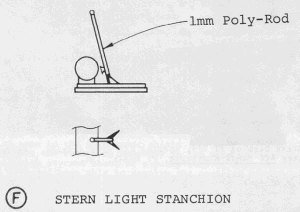
Clean up and add the balance of the deck fittings at this time. I made a new stern light stanchion from 1mm rod drilled to accept the shank of a No.2 Botany Specimen Pin. These pins, available in school supply stores, are very useful, since the heads are small and round and do not look like straight pin heads when used for such items as throttle knobs, vehicle levers, etc. Figure F shows the stern light stanchion with deck braces made from .010-inch sheet. I also made new lifeline stanchions from .75mm rod drilled through with a #80 drill bit. The forward jackstaff was often not rigged. I left it off, but added a jackstaff socket from 1/16-inch Plastruct tubing.

The cockpit armor shields and instrument panel can now be assembled. Inside the cockpit, a 1/8-inch wide step from .020-inch sheet should be added to the port armor shield, approximately 3/16-inch above deck level. The kit searchlight is inaccurate and misplaced, but its head can be used in constructing a new searchlight assembly per Figure G. The searchlight is mounted as shown on my model, after filling the hole in the kit's deck intended for the searchlight mounting. From .015-inch sheet, make six new deck cleats to replace those removed earlier. I glued the short legs to the deck first, then shaped them after drying, then added the horizontal bars and finished shaping after the liquid glue was dry.
After cleaning off mold lines, the mast and mast brace may be glued in place. Atop the mast I added an anchor light from clear sprue, capped with a disc of .010-inch sheet. Diagonal bracing wires from stretched sprue, thin wire or monofilament line should be glued across the mast lower sections at this time.
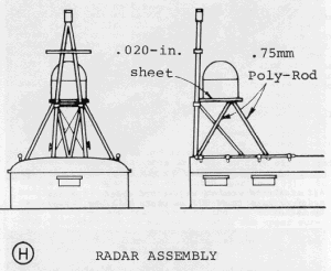
PT-155 was a section leader's boat and had one of the early experimental radar installations. The antennas for these units were mounted to a platform aft of the mast and were braced to the day room overhead. I used .75mm rod for the braces. Figure H shows this configuration. The radar antenna housing was constructed from part of an extra aircraft drop tank from my spare parts box. To be really authentic, the dome could be constructed from styrene formers covered with cloth or tissue, since the real item was canvas-covered over wooden ribs.
Torpedo Tubes
The tubes are quite accurate in size and shape. Unfortunately, the tensioning located on each side of each tube are molded integrally with the tube. Carve them off after gluing the tube halves together and replace with lengths of .75mm rod or .024-inch wire.
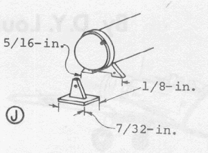
The tubes can be shown in either the stowed position inboard, or run out to firing position. Either way, you will have to manufacture a tube stop set for each set. Figure J shows the two-part set. Build both the deck stops and the tube brackets from .015-inch sheet, drilling through the tube brackets with a #76 drill bit. After the tube brackets have dried, temporarily mount each tube in whichever position you chose and glue the deck stops into place either aligned with the inboard or outboard holes in the tube brackets. A tiny drop of Elmer's Glue applied to the forward face of each deck stop will simulate the locking pinhead.
Armament

As previously mentioned, PT armament varied widely, but it was still 'standard' on many boats, including PT-155 in mid-1943. The 20mm Oerlikon gun (part 54) can be acceptably modified. The magazine should be cut off and offset to the right side of the breech mechanism forward of the pivot. Sharpen up and drill out the sights and drill out the muzzle with a #78 drill bit. I cut shoulder braces from .020-inch sheet and mounted them to the rear surface of the breech with .75mm rod. These details are shown in the model photos.

The two .50 caliber machine gun assemblies require considerably more effort, but the results are most pleasing. Discard the kit machine guns and substitute two pairs of aftermarket .50 caliber aircraft machine guns. Clean any molding lines from each gun and drill out the barrel holes and muzzle. I joined the guns with a rectangular section open-bottom box made from .010-inch sheet. If you are not screaming obscenities by this time, you can fit an empty cartridge collection bag of tissue or cloth, below this open box. Cartridge feed guides, also from .010-inch sheet and shown in Figure K, are glued approximately 1/16-inch out from each side of the machine gun assemblies.
The inner ring of each turret, with the machine guns, rotated, while the gun limiting railings remained stationary. The kit parts (#21) are not quite accurate, but modification would require more effort than I was willing to go to for a slight improvement. I cleaned up the turret rings, including inside the gunners' backrests, and used them as is. New gun limiting railings are now bent from soft .024-inch wire and assembled with cyano. Glue or tape the turret rings to a dowel or some other handling device during this process or you will be constantly referring to the author's or the kit manufacturer's maternal lineage. Glue gun mount railings to the inner rings, and make a new gun limiting railing for the 20mm Oerlikon from the same material, using part 52 as a guide. From scrap box materials, make up four .50 caliber ammunition boxes to fit inside the turret ring as shown in the photos. After painting the model and the guns, mount the machine gun assemblies on the inner railings and, if desired, attach cartridge belts from thin cardboard strips and short lengths of stretched sprue.
Painting & Marking
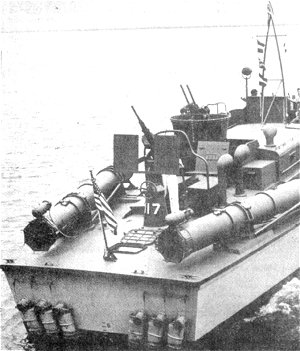 |
| Stern view of PT-117, showing aft area details. Photo from All Hands Newspaper. |
The Elco boats came from the factory painted overall "battleship grey." In the Solomons, however, the boats were often moored under or near shoreline trees and vegetation, and the grey color was too conspicuous. No official Pacific camouflage scheme existed at the time I show PT-155, and each crew repainted its own boat during the campaign with whatever materials it could scrounge. To one of PT-155's crewmen, J.M. 'Boats' Newberry, I am obliged for information on the vessel's colors during the campaign for Rendova and New Georgia islands.
PT-155 and other boats of Squadron 7 & 9, including PT-109, were simply sprayed overall with a green paint from some local source, probably USMC. The green became lighter when applied, apparently due to the grey undercoat oxides. Over this, PT-155 was painted in random black patches. No standard pattern was used.
I gave my boat a primer coat of Camouflage Grey. Priming in not absolutely necessary, but it allows the modeler to spot any 'boo-boos' and to touch them up before finish painting. Mask the windows with liquid latex before priming and follow up with two or three thin coats of Floquil Dark Green (M36). For the black patches, I hand-painted Humbrol Black (HM11). I added white numbers from Letraset sheet M35 as the boat's only markings.
After weathering to your taste with grime, silver, grey and tiny helpings of rust, spray the entire boat with Floquil Flat Finish or any other semi-gloss coating. Let the boat dry for a couple of days, then spray on several coats of Floquil Dio-Sol dirtied with black paint, to pop out the small detail and add emphasis.
With that you are ready to remove the window masking and add final details such as lifelines, radio aerial, halyards, wheel, torpedo tubes and guns. I installed a windshield of clear 1/32-inch styrene. The life raft on the forward deck is something of a problem. It comes with attractive extras such as paddles and cans molded to the raft bottom. I covered these by lashing a boarding net of painted gauze over the raft. Otherwise, scrape or sand the bottom smooth and paint the entire raft to match your color scheme. Paint the searchlight interior aluminum and insert a lens of clear styrene or acetate. My model of PT-155 is shown without rudders or propellers because it is to be placed in a water diorama formed from clear casting resin. If you choose to display your model on a stand, add these underwater components now and your very own piece of naval history is complete.
Photo Gallery
 |
 |
 |
 |
 |
 |
BIBLIOGRAPHY
- Bulkley, R.J., Jr. At Close Quarters.Washington, Government Printing Office, 1962.
- Cooper, Bryan. PT Boats.New York: Ballantine Books, Inc., 1970.
- Donovan, Robert J. PT-109.New York: McGraw-Hill, 1961.
- Keating, Bern. The Mosquito Fleet.New York: G.P. Putnam's Sons, 1967.
- IPMS UPDATE, VII, N1, July 1975.
- IPMS QUARTERLY, VII, N3, Winter 1975.
