Pro Modeler 1/48 P-47N Thunderbolt Kit Build Review
By Kelly Jamison
| Date of Review | March 2021 | Manufacturer | Pro Modeler |
|---|---|---|---|
| Subject | P-47N Thunderbolt | Scale | 1/48 |
| Kit Number | 5929 | Primary Media | Styrene, Photo-Etch |
| Pros | Unique subject with unique engineering | Cons | Cockpit undersized, landing gear is molded to wheel wells |
| Skill Level | Intermediate | MSRP (USD) | OOP |
Build Review
I usually do not write histories on the modeling subject unless they are a rare aircraft or an uncommon specific aircraft. I figure if you got this far to look up P-47’s then you might know a little bit about the Thunderbolt, but I will talk a bit about the P-47N specifically since it really was a quite different. The N model was the final alteration of the P-47 series of heavy weight fighters and was designed by Republic to have the performance of the ubiquitous P-47D but with tailored modifications needed for very-long range (VLR) flight operations in the Pacific Theater. The wings were bigger despite the tips being trimmed off. The internal fuel load went from 305 to 556 gallons and the ability to carry 165-gallon long range tanks added the ability to conduct 9+ hour long missions. The P-47N carried on with its duties well past WWII in the Air National Guard as the F-47N and was even used by the All-Weather Flying Center, in a very colorful and attractive scheme.
After swearing off old Monogram (Revell) kits, what do I do? I immediately turn my attention to the Revell-Monogram Pro Modeler P-47N Thunderbolt in 1/48 scale. Consider it a character flaw. I looked it over and thought the kit had some unique design elements. The landing gear being molded to the wheel well sidewalls is one of them. The bottom wing to fuselage joint is another unique feature that allows the wheel wells to be done without a seam going through them. The interesting spine antennas, the separate machine gun barrels from the wing faring, the tail wheel mounting area. Disappointingly, all of them became issues. Not insurmountable at all but issues non the less.
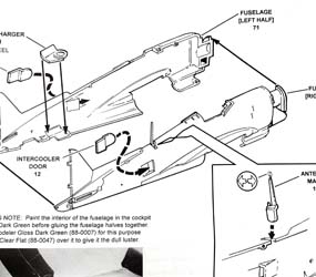
Step 1, Fuselage Assembly: Your first task is to attach the intercooler doors and supercharger onto the fuselage and then glue the two halves together. I must admit that the intercooler doors Part #12 were designed in a peculiar way. You do not get a positive feel for where exactly they are supposed to be glued to on the inside of the fuselage. You will figure it out, but it just seems “stick here and hope I am right” was my best method for getting those parts in place. This is where I started to notice that the directions are vague in some of these key build steps. The supercharger got sprayed steel silver and a dark wash was applied to bring out the small blades along with heat tinting the area. Again, not a real positive feel where it goes but you will get the idea of the general fit. Now the fuselage halves are ready to glue together. Fast few steps but it does make sense when you see it.
Be aware of the unusual rudder design. Both sides of the rudder are fully molded onto the left side fuselage and only ¾ the way down, on the right side. The rest of the rudder on the right side is molded to the right fuselage half. I am not sure why, but this caused an extra gap on the right side of the rudder after the fuselage halves were glued together that needed to be filled and sanded. Next came another little dilemma, the Antenna Mast, Part #13. It slides into a slot in the right half spine near the long rudder strake. This makes it near impossible to fill and sand and a prime candidate for multiple attempts at breaking off the antenna during assembly. I opted to cut off the antenna for later placement and then glue Part #13 in with gap filling superglue. Just like that you are on to Step 2, Cockpit Assembly.
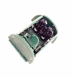
Although not terrible, the cockpit assembly looked a bit undersized and soft in detail. You could easily use it if you wish. The kit even comes with a pilot if you want to pose your model in that fashion. I had a Cutting-Edge P-47N resin cockpit that I had been saving for some time and this was the time to use it. The cockpit went together quickly but the seat rails were very delicate, and the instrument panel did not have the photo-etch with film instrument backing like we have become used to with other cockpit sets so it takes a little more painting and detailing. I dropped in the finished cockpit and glued into place with white glue. This allows a few minutes to get it adjusted exactly right. After the white glue has dried, I then lock it into place with a few drops of superglue along the fuselage walls. In a bit of irony, I lost the control stick during the sanding and painting process, so I used the kit control stick, which, to me, looked better. Off to Step 3, Wing Assembly.
The bottom of the wing is one entire piece with the ailerons and only the front section of the flaps engineered as a single piece. I am not sure why they did the flaps like that, but it causes problems later in the build. At this point you have the option of drilling out the rocket pylons and the bomb/fuel tank rack mounting holes. Depending on how you want to present your plane depends on which holes you want to drill out. The instruction sheet calls out the decal choice for “Sack Happy” is a P-47N-1-RE which was an early production P-47N and not equipped to carry rockets. But some of the aircraft were field modified to carry rockets and were redesignated as P-47N-2-RE. The best thing to do is to check your references for the exact aircraft you wish to build.
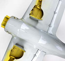
Here is another one of the unique parts of this build. The landing gear Parts #32 and #33 are molded in one piece with the back wall of the wheel well. The problem is there is not a positive feel to exactly where the gear is glued down to. There is a lot of play to get it in place and a little bit off here adds up to a lot there. This causes the two gear struts not being symmetrical with each other. I used liquid glue so I could adjust the exact angles and then used superglue to get the wheel well walls stronger. Even after all of this, the gear itself was flimsy and just did not have a solid feel, not to mention it was constantly in the way for the remainder of the build and got bent and almost broken off many times. In hindsight, I would have cut the struts off and glued them back on at the end of the build. The rest of the wheel well got tacked into place. The inner wheel well walls have the small landing gear covers molded into them. They looked good but got in the way while sanding the wing joint later. Everything got a coat of Zinc Chromate Yellow by Model Masters Acryl.
It was already time to glue the wing tops on. Remember these tops had part of the flaps molded into them on the bottom side. This made them awkward to glue into place and left big gaps in the bottom of the wing flap area that had to be filled and sanded. The wings got glued together with lots of clamps being used to get them all in place. I did not like the gun barrels. They looked under scale and easy to break off, so I went ahead and glued both the gun leading edge faring’s into place without the gun barrels. I had confused the right one with the left one, but the fit was so poor that you really could not tell which was which. They both needed to be filled in and sanded smooth. I would later use micro-tube to finish off the barrels during final assembly. The mating of the wings to the fuselage was problematic too. When you would get the front to line up, the back would be off. When you would get that lined up, the wings were no longer level. When you got that straightened up it would cause too big a gap in the upper wing roots. Lots of adjusting, filling and sanding was needed to keep everything in line. You will spend a little time here for sure.
I also jumped a few steps and got the wing tip lights done. I took each lens and drilled a little hole in the mating surface side of the clear piece then put a dab of paint in there to represent the little light bulb. Easy technique and looks good. Always remember “Red Left Port” and you will not get those colors backwards. The clear piece got superglued into place. Sanded into shape and polished. I put a piece of tape on each light to protect the clear pieces. Off to Step 4, Tail Assembly.
I held off assembly of the horizonal tail surfaces on until I could fix that big seam in the rudder on the right side. I sprayed the assembly down with Badger’s Stynylrez Grey primer and it really showed that rudder seam, so I went back over it again with some putty and smoothed it out. It was not that big of a deal, just a strange thing to have to contend with. I kept the tail wheel assembly off until near the end of the build. It made it much easier to paint and not break off the tail wheel. Quickly we are off to Step 5, Engine Assembly.
The engine looked a bit under scale to me, but it looked fine inside the cowling. Part #61, the rear half of the front cylinder row, is so close in casting to the rear half of the back cylinder row that they are easily confused. The easiest thing to do is built the front row first then the back row. The propeller shaft, Part #10, is really associated with the Gearcase, Part #101, and not the cylinder banks like the directions point out. I ended just gluing the propeller shaft into the gear box. Also, the drawing has the cylinders being aligned and not off-set like they should be which adds to the confusion. Everything got detailed out from reference photos I have and put off to the side for later. The right and left exhaust waste gates fit right into indentions in the bottom of the fuselage nicely, but the gap is a little on the large side and distracting. I ran some Tamiya primer along that seam to just tightened them up a bit. The nicely engineered single piece cowling got the casting lug cut out and the edges sanded to blend, and the inside of the cowl got painted Chromate Yellow. Part #5, Airflow Divider, showed signs of being undershot (along with landing gear covers and spots on the fuselage that you can see with putty before I sprayed with primer.) but you cannot really see the sunken areas with the engine in the cowl. I sprayed the airflow divider, that sits inside the bottom of the cowl, silver per instructions. But like a lot of this build, there was not a positive feel as to where exactly it is supposed to be glued to the inside cowl. I fit it a few times with the engine to get the spacing and alignment correct but it was strange. Like something like from a short run specialty kit and not from a major manufacturer. Next step is Step 6, Main Landing Gear.
The torque links get glued on next, but I had a hard time figuring out which side of the linkage was up and exactly where the part was supposed to be affixed to. Again, with that same theme on this kit. I held off on the gear doors until I painted the entire plane. I noticed that the gear doors lacked any detail and was short shot because they were sunken and needed to be puttied and sanded smooth. I put rivet detail on them to help spruce them up a little bit. The kit wheels are crosshatch pattern and are exceedingly difficult to sand into all those treads. I guess you could sand them smooth and that would not be out of line with these planes being used on crushed coral runways. But I got a set of Ultracast 48125 resin wheels to take care of the problem anyway. I airbrushed them black and used silver sharpie marker to get the hub and spokes painted on. I like the effect it gives. That got put off to the side along with the landing gear doors for later assembly.
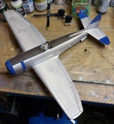
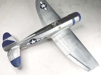
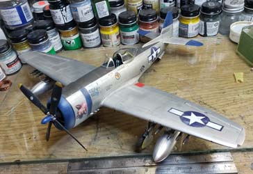
The instructions call out for Step, 7 Underwing Stores. I saved this step to the end of the build. Now it was time for paint. I used Alclad polished Aluminum and Alclad Chrome to give some tonal changes to the bare metal finish. It is exaggerated at first, but the dull coat will mute the reflective properties of those two colors to replicate a nice, weathered aluminum. After drying for a while, I painted Model Masters Olive Drab for the anti-glare panel and used Tamiya X-4 Blue for the accent colors on the tail, stabilizers and cowl flaps. In the bottle it looked like a perfect match but dried much darker. The whole thing got a coat of Alclad Aqua Clear to get a good gloss coat in preparation for a set of Kits-World War Birds series KW148088 P-47N decals.
I chose 44-88820 ‘Red E Ruth’ flown by Capt. Don Stuck. First thing I noticed was the fuselage star and bar are not sectioned out to work with the supercharger inner cooler doors. Careful cutting had to be done to get a good fit. They did respond well to the Micro-Sol/Micro-Set system. Although I used Mr. Mark Softer and it was way too hot of an emulsifier, literally melting the bottom wing star and bar decal. Be extra careful if you use a hot emulsifier like Solva-Set or Mr. Mark with these decals.
Once all the decals were thoroughly dried, I took some 5000-grit micromesh sandpaper and slowly started to weather the decals. This is a painfully slow process that can ruin a set of decals in one swipe if you do not use a soft touch and patient hand. I used some fine ground white pastel powder and mixed it very lightly with Future Floor Polish to make a thin white transparent paint and did some weathering on the blue surfaces trying to replicate the harsh Pacific Sun. I like the technique, but the camera did not really pick up the subtle changes the concoction produced. I have been using a dark wash that consist of ¼ Future to ¾ water with a drop of liquid dish washing soap and a few drops of acrylic black and brown. The whole model got a coat of that with a fine sable brush. Another secret I keep is I use the old Alclad silver powder and a cotton swab to touch up any faults I find. There was some tricky overspray of blue right by the nose art that I had to really go slow and try to remove. Then I sprayed Model Master Dull Coat Clear to tie it all together. The prop got the same weather treatment as the rest of the plane and it did not look too bad at all.
Step 7 revisited: I wanted to load mine with the rockets and fuel tanks that a P-47N-5-RE would have. The tanks are just ok. The shape looks good but there are no filler caps! I did not even notice it until after I had painted the tanks. I used the decals that came in the kit to replicate the filler caps, but I do not really think it looks that good. With just a little more effort and a hole punch and some sheet plastic, you can make a filler cap in about 30 seconds. I took the low road.
The rockets were easy enough even though there were 10 of them to do. I airbrushed the missile heads olive drab and let it dry then masked them off and shot the rocket body silver and then used my Silver Sharpie for the mounting stubs to give that tonal change needed. The bombs went into the spare parts bin. Getting everything to line up was difficult. Once you got all the missiles lined up on the horizonal, they would be off on the vertical. Get them both lined up and they would not be parallel with each other. The drop tanks had the same problem and because they were so big it was easy to tell when they were not lined up properly. There are also these small sway braces at the tail of the drop tanks that were frustrating to get on and lined up too. Vague instructions and fitting points compound the problems in this area.
Time for the wheels. I got some weathering oils and sand colored pastel chalk mixed with Future Floor Polish to make a thin slurry to acquire that “some mud in your tires” look. I drilled out the center hubs to fit on the kit landing gear axles. Let it dry and when I sat it down on its own weight, the wheels were all over the place. It took a few attempts, and I was still having problems. Deadlines wait for no man and I took the pictures with the right wheel still being a bit off. I could not take it one night after the photos were “in the can” and bent them even further into place. Much better but it is something you will have to tackle on your build. I also cut out micro tube for the machine gun barrels. That was easy and hard at the same time. If you put glue on the end of the barrel, the shroud that goes around the barrel will scrape it off. The easiest thing to do was to use one of those little squeeze bottles with a hypo needle and fill it with white glue. Pour some of that into each machine gun barrel port and then place the barrels in one at a time. I noticed the barrels not being aligned very well after photography was done. I straightened them out, but the build was starting to wear on me. So many things had to really be perfect, or they stood out like a sore thumb.
The pitot tube is a bit unique in that the pointy end has flat sides and is not tube shaped but due to poor mold alignment, it had to be reworked to be passible at all. I also noticed that the condition lights (the yellow, green and red lenses) on the bottom of the wing were just decals too. I never noticed until it was too late, or I would have probably scratched built the lenses myself. I put the decals on and then hit them with a dot of MicroScale Krystal Klear white glue to replicate each of the glass lenses. It is passible but a cheap trick for sure. The double antenna on Step 9 has no positive mounting areas to get them lined up. I ended up using white glue and gluing one antenna on at a time. You must really be patient and take the time to keep them aligned while they dry. The canopy got masked off and sprayed in the same fashion as the fuselage. I used the Cutting-Edge gunsight but really the kit gunsight will work fine. I just added to the complexity of an already trying kit.
In the box, this kit looked like a quick easy build but as I progressed through the different assembly stages, more and more shortcomings popped up that I did not see coming. I thought the preset landing gear would make life easier and the opposite happened with them constantly being in the way and complicating wheel alignment. There were too many parts that did not have a positive mounting point or were vague in how they were supposed to fit. Even though the aftermarket cockpit looks great it was a lot of extra work that really was not necessary. It looks great sitting on the shelf, but all the pointy things, barrels, tanks and antenna will make this a sure loser in a contest. Eye candy only goes so far. The way to look at this build is to ask yourself how much time and effort you want to invest in the build. Throw it together and hang from the ceiling, a decent 3-footer or a show winner. Each will yield you a different result at a cost.
