Moebius Models 1/6 Robot B9 Kit Build Review
by Steve Causey
| Date of Review | February 2014 | Manufacturer | Moebius Models |
|---|---|---|---|
| Subject | Robot B9 | Scale | 1/6 |
| Kit Number | 939 | Primary Media | Styrene, Photo-Etch, Vinyl |
| Pros | New-tool kit | Cons | Nothing noted |
| Skill Level | Experienced | MSRP (USD) | $54.95 |
Build Review
Moebius has released the B9 Robot from Lost in Space and sci-fi modelers have warmly received it worldwide. I'm no exception; I was excited to hear that I had one on the way to review. I started on the kit the day it arrived. For a look at the kit out of the box, look here.
You get crisply molded parts in gray and clear styrene, three photo-etched parts for the lower torso vents, and vinyl parts for the legs and arms. One tiny decal sheet is also included for labels on the clear buttons in the programming bay. The instructions are great, easy to understand and clearly written and drawn. I found little or no mold seams on any of the parts. The parts fit together so well that too much paint can affect the fit. The clear parts are lovely; crystal clear with no cloudiness or scratches. The vinyl parts have tiny mold seams, and I decided not to sand them because I didn't want to mar the shiny surface of the vinyl. I had decided not to try painting the vinyl parts due to possible paint adhesion worries and besides they look really nice unpainted.
For this build I also added the Sound & Light kit From Starling Technologies. It's a plug and play lighting kit that also has a sound board with 17 different phrases. For a closer look at this kit, look here.
The instructions have 33 well-illustrated steps. I needed to jump around in the assembly sequence to accommodate the light kit installation. The B9 model kit itself was designed to allow the builder to light the kit with a minimum of fuss.
I first started with the parts of the kit that would need light blocking paint to prevent light bleeding through the plastic. Make sure you wash all of the kit parts very thoroughly as I had some oil contamination problems, even though I first soaked the parts in purple power, then hot water and dish detergent. After a second washing they were fine.
After the parts had dried in the sun I applied flat black paint to the insides of the torso parts. When the black was dry, I assembled the torso parts and lower leg parts that would need seam work. When the glue was dry, I shot all the parts with Tamiya fine white primer. This sets up the plastic for the lacquer coats to follow and also highlights the seams to allow me to see the extent of the filling work that will be needed.
To fill the seams I used Squadron White Stuff and Gunze Sanyo Mr. Surfacer as well as many coats of fine white primer. To get a smooth surface was imperative due to the silver finish of the Robot. The worst seams were on the lower legs (right and left tread section assemblies) and these required a few applications of white putty to eliminate the large seams. As I'm working with the seams I'm also deciding where to place the different components of the light kit (power in, soundboard, main board with fiber optic connections). There are quite a few assemblies in this kit that have seams that need to be filled. They are easy to do in subassemblies as you proceed in the build.
Once all the assemblies that needed filling were in primer and ready for paint, I shot them with Tamiya Mica Silver it's an easy to apply durable high gloss finish.
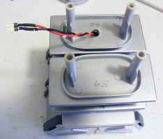
I installed the power lead in the lower left tread assembly and ran the wires up towards the torso. The wires unplug easily from the sound and main boards allowing the builder to install the electronics without splicing any wires.
Next I glued the vinyl knee assembly (part # 70) to the treads using Aileen's tacky glue, a thick strong white glue. It filled in any gaps and bonded well with the vinyl parts. Once I had the vinyl legs (part # 69) installed, I let the white glue dry, and used a heavy can of beans to help clamp all the parts together.
With the leg parts dry, I started adding lower torso parts. I drilled large wire access holes in part # 46 and lower torso # 27. The three torso parts (upper torso, lower torso, and middle torso) are painted but not glued together to allow more work on the wiring installation. The claws and wrists need some seam work as well. I installed the pre painted claws (parts #55 &56) x 2 in the wrists (parts #50&51) x 2. If you are careful the claws can be made to open and close. I masked off the red claws and dressed the wrist seams and then painted them the final color.
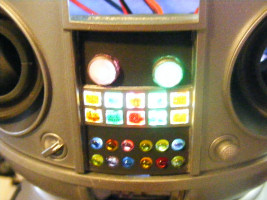
The vinyl arms snap fit tightly into the torso. The only way I could get them to seat into the recess for them was to push my finger down the hollow arm and press the end into its socket. You might be able to change between the two different arm types but I'd recommend using magnets after modifying the arm sockets. At this point, the Robot is glued up to the lower torso section. I ran the wiring from the sound board up into the lower torso and then installed the clear torso vent parts (#1) and the torso programming bay after pre painting the programming bay and drilling a hole for a power indicator light. To aid in light blocking the lower torso vents, I coated the Photo etched parts with Micro krystal- kleer, when that was dry, I painted the PE screens with some light coats of flat black. This gives the illusion of transparency but also helps hide the wiring.
The two main kit parts that need to be modified to allow the light kit to work are part #34 (back plate) and part #15 (button plate). Part 34 needs careful removal of plastic to allow the voice light tube to fit. Part 15 needs tiny holes drilled in the back of the round buttons to allow the fiber optic strands to be glued in. All these mods are explained in detail in the Starling Tech online PDF manual.
I placed the main board in the torso connecting the power leads.
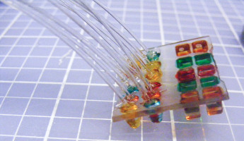
I oriented the four flashing LEDs on the board with the chest light area. I painted the chest light buttons with a first coat of tinted future then when cured, I added more color with the appropriate Tamiya acrylic clear colors.
After all the colors had dried, I attached 12 strands of fiber-optic to each hole in the back of the button plate using 5-minute epoxy. I then added 1/16th" shrink tube to the strands to prevent light bleeding through the different strands and diminishing the random blinking effect. The two large chest lights each get their own blinking led; I made sockets out of tubing and attached those to the backside of the torso.
Now, I had to start lighting the "brain" I wanted to light the seven finger lights (part #5). To do that I needed to replace the kit parts with 1/16th" (1.5mm) brass tubing.
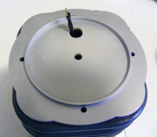
I enlarged the hole in the brain cup bottom half (part # 45) so I could run seven strands of fiber-optics for the fingers and an additional five strands of fiber-optics to light the eyes and bulbs on top of the brain assembly.
After that assembly, all that was left was to polish the upper and lower dome halves and start gluing the torso assemblies together as I worked my way up the robot's body.
As the upper part of the robot was finished I glued the fiber-optic strands to the sockets on the remaining LEDs making sure to get a nice random blinking pattern as I hooked the strands to the different LEDs
The Moebius kit of the B9 robot is a triumph, both for Moebius and for modelers.
If you don't the dress the seams or add lights, you could have a great replica in a few days. Due to the silver finish, some experience will be required.
I spent 100 hours on this build (I was doing the alpha install of the Starling light/sound kit and needed to figure out the installation procedures). With that said, I think 60 hours of effort would get you a museum quality model.
My sincere thanks to Moebius Models for this review sample!


