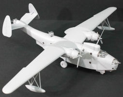
Minicraft 1/72 PBM-5A Mariner Quick Build Review
By Michael Benolkin
| Date of Review | August 2013 | Manufacturer | Minicraft |
|---|---|---|---|
| Subject | PBM-5A Mariner | Scale | 1/72 |
| Kit Number | 11669 | Primary Media | Styrene |
| Pros | Nice detailing throughout, excellent fit | Cons | Instructions are a bit vague (see text) |
| Skill Level | Experienced | MSRP (USD) | $69.98 |
Background
For a look at the kit out of the box and a highlight of the features and options, look here. I was really curious how an all-new-tool Minicraft kit would go together, especially one with as many details as this in the box. As you know, Minicraft transitioned from pattern-based kit design to CAD-based design a number of years ago, but only a few all-new subjects have come out of that transition and they were all much simpler 1/144 subjects. Since we've seen other hobby companies have less success with CAD-based tooling, I had to give this project a try.
Quick Build
Remember that in our quick-builds, I do not use fillers or paints, what you see in the photos is bare plastic. I use Tamiya Extra-Thin Cement for construction along with a sharp set of sprue cutters, hobby knife, and a set of files. Just the basics. The plastic in this kit is similar to that used by AMT/ERTL which is a bit softer and very responsive to the liquid cement. This provides a VERY secure bond and when pressing parts together, the soft plastic does some of its own seam-filling. The liquid cement will be very important in a few steps as we'll discuss.
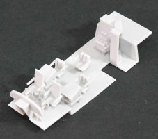
Steps 1-2 - Here we build up the flight deck and here we have stations for the pilot, copilot, flight engineer, radio operator and radar operator, plus an observer. The seats are on pedestals which mount into depressions (not holes) in the flight deck. This first assembly will teach you the time and patience to hold the part to the correct place just long enough for the glue to take hold, which in this case was about 30-45 seconds.
The avionics racks that mount behind the pilots' seats are two frames and a tray - you've got to carefully cement the three parts together, then glue them to the deck making sure that you've oriented the rack correctly, then mount the radio or radar box. What is nice about using liquid cement is that even after careful study of the instructions, I put the rack in backwards and didn't catch it until I mounted the radio. It was a simple matter to pull up the rack as the glue had not completely cured, turn it around and try again. Take a look at the completed flight deck ready for painting and detailing:
Steps 3-4 - In this set of steps, we install all of the windows in each fuselage half as well as the main wheel well, and nose gear well. I thought about skipping these windows and using white glue (which is still a good option) but I wanted to see how well these windows fit. They fit nicely, especially the special shapes that conform to rounded sections of the fuselage.
I was surprised to see how well the fuselage halves go together - here are a couple of shots with the halves together but neither glued nor taped together. There is no warping nor fit issues and this is very nice.
At the risk of repeating myself, careful preparation of each part is very crucial to the success or frustration of this kit. All left-over sprue stubs, ejector pin marks, mold flash (only a tiny bit here and there) must be cleaned away because this model was designed to some very tight tolerances as you'll see. The ease of those two fuselage halves laying together above is a good example.
Step 5 - It is time to install the flight deck and glue the fuselage halves together. There were no issues or surprises. You can see in these close-ups how well Minicraft's design is executed:
Steps 6-9 - Now it is time to assemble the weapons bays that are located in the engine nacelles. The detailing for the side structures is nicely done but pay attention to the instructions on how to orient the parts and test-fit everything before gluing. I did find an error in the instructions - the forward weapons bay bulkheads are going into the wrong nacelles. They will fit fine, but the surface detailing will be facing in the wrong direction. Part B3 goes into the port wing and B2 into the starboard wing.
There are no locating points on the side frames for the weapons racks (Parts E1) and the instructions show that they go somewhere 'over there'. The bottom of the racks should not extend below the edges of the weapons bay openings. The weapons bay doors are molded closed but a cut line is provided should you want to open them. You can see some nice detailing in there, especially with the upper wing half in place as you see to the right. Without any weapons in the kit, I'll keep these doors closed.
Step 10 - Here is what I consider to be the crucial part of this kit - the wing joints. When I viewed the instructions, it looked like the lower wing halves are glued to the upper halves before adding the center section. On paper this looked fine and that is exactly what I did. Don't do this please. The center section has edges that fit under the upper wing halves and should slip into place but with the way the upper surface of each weapons bay must fit into the framework, there is no slipping of anything that will work without damaging something.
Glue the lower surface of the wings to the center section and clamp them into place. Glue the upper halves of the wings onto the lower surfaces but do not glue the upper wing halves to the center section (red arrows below) yet. Let the other glue joints firm up first and handle this assembly with care as this wing arrangement is very weak at this point.
When everything was dry and cleaned up, I put the wings up atop spray cans, loaded the wing seams at the red arrows with liquid cement, then added ballast to the center of the wing to flex the joints closed. The result is a very strong wing that I test-dropped a few times and is ready to be handled under the full weight of the completed model. The flex-dry didn't change the dihedral as the joints were pretty tight to begin with but I wanted those seams to be solid plastic after the glue had cured. You can see in the image that even with all that weight, the wings are holding their shape perfectly.
Steps 11-13 - Before I started on these steps, I dry-fit the assembled wing onto the fuselage and found that the center section 'cap' no longer fit onto the corresponding recess atop the fuselage. The culprits were the edges of the inboard flap wells that are part of the lower wing halves that protrude inside the cap after assembly (red arrows below). The only remedy was to file these protrusions flush to the sides of the cap and a nice smooth fit was restored.
The lower engine air intakes (oil radiator) are five parts each. In theory the two halves of the intake go together, the intake radiator face goes inside followed by the exhaust radiator face and exit duct. Unfortunately the intake radiator face (Part 43) will no go inside the intake once the halves are glued together. Either add yours before gluing the intake halves together, or do what I did and discard the parts. The rest of the subassemblies go together fine (seen below between the open cowl flap sections).
The flaps and ailerons go together next and these were uneventful with one exception. The hinges on the trailing edge of the wings are T-shaped and the control surfaces assemble around them. One of the inboard hinges of the inboard flap sections was evidently changed to an L-shape on both sides and this new shape doesn't fit inside the inboard flap halves. The solution is simple, trim the lower leg of the L to match the length of one leg of the adjacent T. The inboard flaps go over this change without any further problems.
Steps 14-16 - These steps tackle the horizontal stabilizer, vertical stabilizers, elevators, rudders, and reinforcement struts. These all went together great and the subassembly added to the fuselage.
Steps 17-19 - Next were the outrigger floats and this looks a little daunting when you see the steps. The instructions have you install the struts (which fit nicely into the recesses under the wing), assemble the floats, then install the floats on the struts. I suggest a slightly different approach: assemble the floats, install the struts under the wings, and while the glue is still setting, install the floats. This allows for the strut angles to be adjusted before the glued parts harden into place. It worked very well for me.
The engines and cowlings go together next and here is another potentially frustrating step as there are sprue stubs inside the center sections of the engines and cowl flaps. Since the gear box front has a tube that the engine banks and cowl flap rings slide onto, and since the fit is very precise, you're going to spend lots of time cleaning out and smoothing out the center sections of these parts. On the other hand, I used my sprue cutters which could only reach a part of the stubs and cleared away what I could. Next I used a model chisel to cut the stubs almost down to the surfaces with ease, then a quick run with a rounded file finished the job. The engines are installed.
The instructions have you select the propeller you'll be using in this project, then suggests waiting until after painting to install them. Sound advice.
Steps 20-22 - The turrets turned out okay for me but I was a bit perplexed that the guns in the dorsal and rear turret were molded separately from the inter-connect shaft that binds them together. The parts fit together fine, so I glued them together, ensured that the gun parts were vertical and that each subassembly formed a square 'H' and set them aside to harden.
The nose turret has a part that fits inside the bubble to represent the gun breeches, but then you glue the external portions of the gun barrels to the bubble. I'm not convinced with this one but it looks okay.
With the H assemblies dry, the top and rear turrets go together fine. The transparencies are front and rear and you might be tempted to glue them together - DON'T! Hold them together and mount them to the turret ring. Carefully add cement to the turret ring and let capillary action spread the liquid glue. Set these aside to dry. This keeps the glue from crazing the visible portions of the clear parts and the bond to the turret ring with keep the clear halves together.
Steps 23-26 - Next is installing the window and shutters for the bomb aimer's position in the lower nose. I opted to keep mine closed.
The landing gear is next and this was relatively uneventful. You were told to open up flashed over holes in Steps 4 and 5 which the main gear struts plug into. The nose gear goes together nicely and again was uneventful. The nose gear doors have hinge tabs on them but good luck getting those into the narrow confines where they're supposed to go. I trimmed the tabs on one end of each door down to a small stub, inserted the door hinge with the longer pin into the corresponding spot on the wheel well and the other hinge pin stub snapped into place. Add a touch of glue and move on.
Steps 27-28 - This is where we go through the final assembly steps with the turrets, cockpit enclosure, antennas and propellers. The turrets all drop into place though inserting the nose turret popped the front fuselage seam. This was easily rectified.
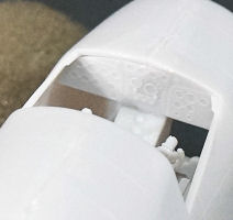
The canopy enclosure is supposed to snap into place but it doesn't quite fit. I had to do a little filing of the front edge of the clear part and the corresponding edge over the instrument panel before it finally dropped into place. I heard a gratifying snap as I thought the part dropped into place but it turned out that the sound was the hairline crack I created in the windscreen. A little more careful filing and I finally got a clean fit.
As you see in the images below, I have a lead weight on the nose. The instructions tell you in Step 4 to add one ounce (28.35 grams) of ballast to the nose. I didn't install any ballast in the kit just to see how it would balance and that weigh is exactly one ounce. It is just enough to keep the nose gear on the surface. This mass needs to be installed ahead of the cockpit/behind the nose turret. Any further aft and you'll need more weight to compensate for arm and moment.
Conclusion
Here we are with Minicraft's first major new-tool kit and she is a beauty. None of the items I brought up above are serious, but I'll emphasize again that the ease of assembly is directly proportional to the effort you apply to cleaning up any sprue stubs, flash, or ejector pin marks. Dry fitting is important here as you'll see the fit is quite precise and one little flaw will mess things up in a hurry.
What is also interesting are the parts that are left over. I've already had a few folks point out the wheel well covers that are on the trees which are plugs to create the non-amphibian PBM-5. There are additional parts which provide a different nose fairing, plugs to cover turret openings, and other options that show that we'll be seeing other variants of this tooling coming in our future. One person asked why they'd to the PBM-5A with only 40 examples as the first release? When have you ever seen a model company release the best variant first? Patience Grasshopper...
My sincere thanks to Minicraft Models for this review sample!


