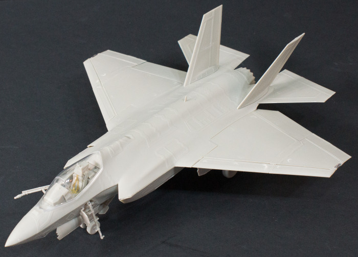
Kitty Hawk Models 1/48 F-35C Lightning II Quick Build Review
By Michael Benolkin
| Date of Review | August 2014 | Manufacturer | Kitty Hawk Models |
|---|---|---|---|
| Subject | F-35C Lightning II | Scale | 1/48 |
| Kit Number | 80132 | Primary Media | Styrene |
| Pros | First kit of this subject | Cons | See text |
| Skill Level | Experienced | MSRP (USD) | $61.95 |
Background
For a brief discussion of this subject and a look at this kit out of the box, look here.
The Build
Before I got underway, I was trying to sort out which parts tree was A, B, etc. The diagrams at the front of the instruction booklet help, but once you start removing parts, none of the trees will look like that any longer. Kitty Hawk didn't put a tab in a corner of each sprue tree with a big 'A' (or whatever), but if you look closer, you'll see each sprue tree does have a small tab with a serial number on it and each serial number ends with a letter suffix. That suffix is your sprue tree identification (A, B, etc.)
I started by test-fitting the main fuselage parts and was pleased with the overall fit of the model though there are touches of flash here and there that need attention before assembly. There is also a phenomenon where some stubs have been pulled out of the parts where the ejector pins pushed the sprues out of the mold and these are simply snipped off with a sprue cutter. The most unique problem were the high-pressure air pins that are also used to remove parts out of the mold. The fuselage halves had the tell-tale 'nipples' left over that needed to be removed.
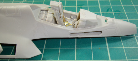
I decided that this would be a quick build rather than a full build with filler, paint, and markings. I wanted to see what issues remained from the F-35B build I did a few years ago and what has improved. Following the instructions, I started with the cockpit. There are two cockpit tubs in this kit and we use the new one made for this release (Part E25). Unfortunately the holes for the throttle and stick were not molded into this tub so I used the old tub as reference and drilled holes with a pin vice.
I didn't notice it right away, but the instrument panel partially slid out from under the coaming/cover but with the molded-in tab, it doesn't sit very far back in any case. As a result, the center pedestal that sits between the pilot's legs wound up interfering with the ejection seat, so as always, keep dry-fitting and testing your parts and subassemblies.
I assembled the nose gear well and weapons bays per the instructions and installed them in the lower fuselage half. Please ensure that any flash or ejector pin stubs are removed and filed flush to the surface as even the slightest imperfection will cause problems.
Here is the engine and while it has nice details, you won't see any of them after assembly. Even the compressor face will be all but invisible down those intake ducts.
I assembled the intake ducts and installed them in the lower fuselage half. While I did glue the ducts to the intakes (and clamped them) and to the weapons bays, I didn't glue them to the engine nor have I glued the engine to the fuselage and this will save the build a little later.
Here are the main wheel wells in place and in the photo to the right, you can see an example of those ejector pin stubs that need to be removed.
I installed the air refueling boom bay to the upper fuselage half per the instructions but here is where I diverge from the instructions. The instructions have you glue the cockpit tub to the nose wheel well but there are no locating tabs, pins, or anything that will align the tub properly. I glued it into the upper fuselage half while the air refueling boom bay was still not completely set so I could adjust both parts for a solid fit. Here is where the fun begins (not).
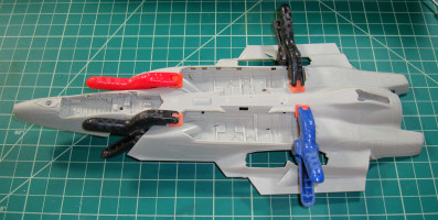
I removed the ejection seat out of the cockpit tub and start dry-fitting the upper and lower fuselage halves. Starting from the rear, the fit is good around the afterburner/stabilator area but there are obstructions around the wing roots. The first step was to remove the engine and cut about 1/3 of the length from the upper and lower fuselage locating pins from the engine. The fuselage halves fit a little better but I wound up filing the upper intake junction down where the ducts meet the engine. When this was a bit flatter, the fit improved. I set the engine aside while I continued to test the rest of the fuselage.
The next challenge was the upper intake joins molded into the upper fuselage. Where the lower fuselage had a nice squared joint to mate the intake ducts, the upper fuselage has a curved surface that interferes with the ducts (see the red arrows above). It took a little file work to clean up this area and again the fit is better.
The final challenge was the cockpit area. It may have been operator error with the nose wheel well but the cockpit floor interferes with the top of the nose wheel well. The nose wheel well is seated as deeply as it can go and ditto on the cockpit tub. I filed material off of the bottom of the cockpit tub and off of the corresponding surface of the wheel well but I just couldn't get a seamless fit. I think it will be easier and safer to work the tub and wheel well parts before installation to get them as thin as practical when next I attempt this project.
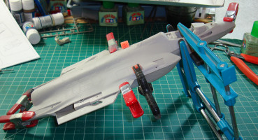
It took a bit of time and effort to get here, but the engine was reinstalled and the fuselage halves are together. Only a bit of filler will be required. The wings go on next and gone are the problems from the F-35B wing join. The F-35C inner wing panels are assembled per the instructions and slid into place on the fuselage. A wee bit of filler will be needed at the wing joints when finished.
You can see in the image above that the leading and trailing edge flaps are installed on the inner wing panels as are the vertical stabilizers and horizontal stabilators. I thought about building this with the wings folded and test-fitted those parts, but the greater challenge would be to build the wings extended to see if there are any problems there. In the image above, the outer wing panels are also installed and these went on with no issues.
Here is one bit of mystery. These are the flaperons for the outer wing panels. As with most of the flight control surfaces, these aren't done in halves rather most of the part is done on the upper surface with an insert used on the lower surface as seen above. If you look at the flaperons that go on the trailing edge of the outer wing panels, the inserts aren't molded to match the corresponding recesses. This isn't a major problem as a little filler will erase the problem and we'll be using filler here and there anyway.
Look from the underside of all of the horizontal flight control surfaces and only a little filler will be required. I've installed everything in the neutral position but you will be able to remove the locating tabs on each of the flight control surfaces and pose the flaps and flaperons as desired. The stabilators will take a little more work to replicate the hinge with the stabilators drooping.
These shots show the remaining slight gaps after working the intake and cockpit/nose gear well thickness challenge. We're not far from a perfect fit and as I said above, a little more work in advance prior to assembly will mitigate this now that we know of the challenge. I'm still not happy with that insert for the gun fairing...
Fotios Rouch had expressed his concern in his Kitty Hawk F-101 build
that some of the parts are small, delicate, and still have mold stubs extending onto the parts. This was quite evident with the RAM fairing around the afterburner nozzle. Using brand new Xuron sprue cutters (very sharp), the one RAM section broke into three parts. These glued back together after filing off the stub and dropped into place. The other section of RAM didn't break, but it wasn't complete either. Like some of the other smaller parts, this was a short shot (incomplete molding). This was very minimal here and in a full-build would have simply been compensated for with filler.
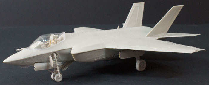
Here's a look at the finished model. I started to pose the weapons bay doors open as I did with the F-35B and changed my mind. Can the model be built with the doors closed? Yes. The instructions don't show you how to do this, but you can piece together the various bay door and door inserts as well as bevel the edges to fit flush with the airframe. I also decided to pose the tail hook up/doors closed and again this worked fine without instructions.
That centerline pod is the experimental 25mm gun pod being flown by the Navy. While the aircraft has an internal gun, I don't know how the internal gun is oriented. Fighters have the gun angled up to have the rounds pass down through the aircraft's flightpath at a prescribed range which is used for air-to-air combat. Air-to-ground guns are aimed along the aircraft boresight. If the gun pod works out, expect to see this on Marine aircraft and possibly Air Force aircraft as well.
Overall this kit is a vast improvement over previous Kitty Hawk kits in terms of design and ease of assembly. Even the instructions have improved with each release and I didn't find any major issues. To put this kit into perspective, Kitty Hawk's quality is comparable to Classic Airframes kits while trying to offer the details of Trumpeter kits. With each release the product improves and it won't be long before we see kits of Monogram or Hasegawa quality in terms of buildability.
Recommended for experienced modelers.
My sincere thanks to Kitty Hawk Models for this review sample!


