Italeri 1/72 Sunderland Mk.I Quick Build
by Michael Benolkin
| Date of Review | September 2012 | Manufacturer | Italeri |
|---|---|---|---|
| Subject | Sunderland Mk.I | Scale | 1/72 |
| Kit Number | 1302 | Primary Media | Styrene, Photo-Etch |
| Pros | Newly tooled version of this subject, nice detailing | Cons | See text |
| Skill Level | Experienced | MSRP (USD) | $78.95 |
Quick Build
For some background of this subject and a look at this kit out of the box, look here.
The Kit
First of all, thanks for your patient emails pointing out a few errors in my in-box review. The dorsal waist guns look like Lewis guns to me but I'm assured they're Vickers K-guns. There were a few other points that were made and the in-box review has been revised accordingly.
I was curious how Italeri was going to do with this subject and decided to do a quick-build. For those who haven't seen one of our quick-build reviews before, the kit is assembled per the instructions using only liquid cement and cyano for the photo-etched parts. No fillers nor paint are used so you can see how the model fits together without hiding any warts in the process.
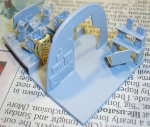
The first step is the flight deck and you have your choice of applying a decal sheet over the molded instrument panel or removing the molded-on detail, add a different decal sheet with instrument faces, then overlay that with a nice photo-etched instrument panel. I opted for plan C - the molded panel without decals. I also skipped adding smaller details like the seatbelts and shoulder harnesses to the pilots' seats but added the larger parts like the photo-etched mounting frames. You can see the crew station behind the cockpit visible through the 'open curtain' but you won't see much of that after the greenhouse enclosure is added over the flight deck.
The lower deck is next with the anchor, winch, and grappling hook.
The instructions have you install the multitude of windows in both fuselage halves. Here is the first step I deviated from the instructions as I wouldn't use these small windows due to the royal pain of masking all of them before painting. Since they are thick enough that you won't see much through them, I opted to leave them off and use another method.
The flight deck and nose compartment are installed in the starboard fuselage half. No problems so far.
The weapons bay is next as well as the upper deck for the waist gunners. Here is our first problem folks. When I installed this unit in the right fuselage half, all was well, and when I dry-fit the left fuselage half, everything appeared normal.
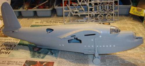
I glued the fuselage halves together and you can see that the sliding nose turret does allow you to see inside the nose compartment (somewhat) but it needs a little more tweaking to keep it from opening up the upper seam as you see in the image. No biggie here, just be aware. The flight deck section fits nicely and you can see already how little you can see into the compartment aft of the cockpit and the greenhouse is not yet installed.
A note about the greenhouse enclosure. I opted to leave it off while I glued up the fuselage halves though the instructions have you install it on one side before bringing the fuselage halves together. If you look closely at the frame where the greenhouse would go, you can see that the Italeri engineers made it sit snugly inside that recess and not reveal a gap in the greenhouse. Pretty ingenious. When I attempted to work the canopy into place, the overhead console that mounts to the underside of the greenhouse extends into the fuselage. This would be fine if you followed instructions but I couldn't get the greenhouse into place with that console, so I trimmed off the part that extends into the fuselage and I was able to get the enclosure into place without damaging the part. Once again, just be aware...
Here's a look at the dorsal seam line between the waist gunners. You can see that the seam didn't close completely and I missed this during dry-fitting. If I were to do this again, I'd trim just a fraction of a millimeter off either side of that upper deck above the weapons bay. That should eliminate any interference when gluing the fuselage halves together in this area.
Here's the assembled fuselage on its beaching gear and I've added the alternative to that multitude of windows - white glue. I normally do this after painting, but since I'm not painting this time around. I thought I'd show you how this would look. The glue is applied with a toothpick and will remain white until it dries.
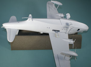
Here is the aircraft with the wings installed and the windows are almost completely dry and already getting clear. This step was done early in the morning before I had sufficient coffee, so I assembled the port aileron and the right wing. I didn't see any problem though I did open up the air intake in the starboard wing root by mistake (it is flashed over) and i stuck some sprue tree into the hole and closed up that error. When I assembled the port wing and installed the starboard aileron, I could see the major mismatch of parts and I swapped ailerons. What was interesting is that there is a difference in thickness of the outer wings around the ailerons. The thickness of the starboard wing was such that I couldn't see the mismatched aileron but when the error was corrected, the ailerons look fine. Drink more coffee, read the instructions...
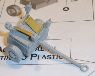
Here is the beaching dolly that goes under the stern of the Sunderland.
So here's the Sunderland assembled. Once again, I skipped the antennas and really small details to focus on the buildability of this kit.
The model goes together very well. The plastic is soft so using liquid cement not only provides a good bond, it also fills in smaller gaps. The only points I'd bring out here are:
- Adjust the thickness of the slide for the nose turret so the seam above it will close naturally.
- Narrow the upper deck over the weapons bay, especially at the rear where the waist gunner positions are to also allow the fuselage halves to close completely.
- You'll note a small gap in the upper left wing/fuselage join. I'm not sure if that was me or not, but if I were building this kit again, I would open up a hole in the ends of the wing and through the fuselage to have a main spar to reinforce that wing/fuselage joint. What is there is fine for most folks, but I think it would improve the rigidity of the model.
- The propeller shafts are also made of that soft plastic. If I were to do this again, I would use brass rod for the propeller shafts.
- Pay attention to the instructions. They're well illustrated but if you get in a hurry, you might miss an important point like number two engine being plumbed and oriented differently than the others.
- Take the extra time to clean up the parts as you remove them from the trees as there is a touch of flash here and there that may interfere with your assembly.
- If you like the idea of using something like white glue but want something clearer, there are some products out there like Microscale's Kristal Klear that is an effective option.
Aside from the points above, this kit was an easy build and I'm impressed with the fit and engineering in this kit. Some folks won't care for the scribed panels which are really visible in this build, but I assure you that they'll all but disappear under paint.
My sincere thanks to MRC for this review sample!


