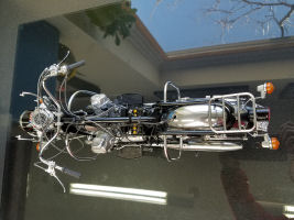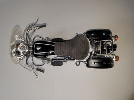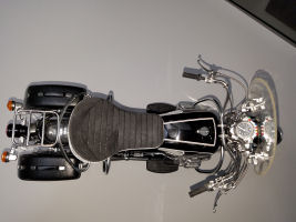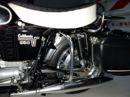
Italeri 1/6 Moto Guzzi V850 California Build Review
By Yvonne Carpenter
| Date of Review | June 2016 | Manufacturer | Italeri |
|---|---|---|---|
| Subject | Moto Guzzi V850 California | Scale | 1/6 |
| Kit Number | 4513 | Primary Media | Styrene, metal |
| Pros | Fully functioning engine, brakes, suspension. Unique subject. | Cons | Connection points for chromed parts will be hard to clean up without ruining the chrome, lots of ejector pin marks and flash cleanup required. |
| Skill Level | Advanced | MSRP (USD) | $475.99 |
Build Review
Please read our first-look
of this kit for an overview of the box contents and first impressions.
As mentioned in our first-look, there is literally a pile of chromed parts/sprues in this kit as the real bike has extensive chrome throughout. The first main decision is to whether you will re-chrome or save/rescue the existing chrome. Given the connection points on the majority of the parts, the cleanup will leave exposed plastic that will need to be touched up. By my experience, these touch ups never look very good, so for me the decision was clear: re-chrome. Since the best look is consistency thru the chromed parts, it is best to re-chrome everything, including the parts that you could save. The next decision is on the re-chrome method, although you do not have to decide on that right away.
I am still split between Alclad or Plastic Chroming services. Thankfully, regardless of the method, the initial steps are the same so you can carry on while you think! In order to re-chrome, we need to remove the existing chrome. There are several approaches here, but the one that has worked best for me over the years is "OFF Oven Cleaner" (not the home brand, but the OFF brand). Normally I de-chrome only few parts at a time so any spare small plastic container will do, but in this case, I had quite a stash of parts to clean so I stole an old cookie sheet from the kitchen. Be aware that the cookie sheet cannot be returned to the kitchen after this operation as it will be destroyed by the Oven Cleaner, but that is why I stole an OLD one.
Spread the sprues/parts on the cookie sheet and spray a generous layer of the oven cleaner all over. Try to avoid the parts overlaying or you won't get good coverage. This process results in a TERRIBLE smell/fumes so a mask is advised (even goggles!). It is also advised to do this in a place where you could close the door as the parts soak, or in a place ventilated to the outside. I usually do this either in our powder room, then close the door and turn the bathroom fan on, or at the garage shop as I can close the door until the smell dissipates. This is a fast process, just a few hours, but it usually has to be done 2 or 3 times to get to the bare plastic.
For this kit, I sprayed the parts once, and after 3 or 4 hours I washed the parts with warm water, scrub soap and an old soft tooth brush. Once the parts are washed and dried, I placed then back on the cookie sheet upside down now, and sprayed them again, going thru the same process. At this point the parts are 90% bare, but you might still see the clear coat applied under the chrome. In order to properly re-chrome the parts, the clear coat has to come off too. You can continue to soak the parts or you can use sandpaper. I used a combination of these methods, whatever I find faster for the particular part.
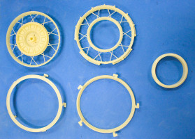
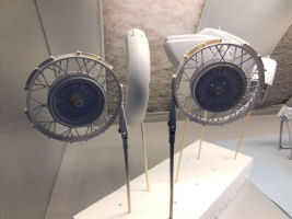
With all the parts de-chromed, I went thru the instructions to see how those parts would be used in the build and when. If I can pre-assemble anything, it is best done before the re-chroming. The trickiest and most time consuming step will be the spoked wheels. Each rim is made up of five parts. By inspection, I decided to glue three of the pieces and leave two of them to be glued after re-chroming due to the angle of connection. The catch here is that you need to align the halves of the rim that contain the spokes and nipples. One side of the rim contains half of the spokes and nipples; the other side contains the rest of the spokes and nipples. So the left and right sides need to align properly so the final result looks like an attractive believable spoked wheel. Unfortunately, when you align the spokes, the nipples become out of alignment, and vice versa. So I picked to align the spokes as it is easier to rebuild the nipples.
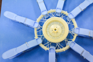
When the rim halves were being glued together, I noticed they were slightly warped so I decided to use several clamps to get a straight wheel. I left this contraption clamped for 2 days. The wheels looked great afterwards. I lightly puttied the halves with liquid putty and after a day of drying I sanded them off. The idea is to use enough putty to hide the center seam, but not too much that you will destroy the wheel sanding the excess off. I made a little jig for this process as I needed a sturdy narrow sand stick. You also need to sand the spokes to clean up flash.
Speaking of spokes, I debated for a while whether to replace the spokes on the wheels for metal homemade ones. But since the spokes are actually in scale, I opted against it. So I was back at sanding the spokes straight to remove any flash and rebuilding the nipples where necessary. On my first pass on the nipples, I used Tamiya Liquid putty which is too soft and thin (came right off, so it was useless). On my second pass I will use tube putty. If that proves to be too soft again, I will try "green stuff". I will use "green stuff" last as it is very hard after it dries and I am afraid to break the spokes when I sand it to shape.
I also worked on the two exhausts. At first I was going to glue each of them together as a sub-assembly, but given the alignment hole on the inside and the connection point to the frame on top, I thought it would be risky to commit to a certain angle only to find out during assembly the alignment is off. Looking at the reference photos, I noticed each exhaust is a three-piece system anyway with clearly visible connection points between the pieces so there was no advantage to pre-assemble. I cleaned and dry-fit both exhaust systems and put them away. I now have a "ready to go" bag of parts to be re-chromed and a bag of parts still to be analyzed. The 'analysis' consists of identifying the part in the instructions and studying the connections and the finished look so a decision can be made on whether to glue it to something else or not before re-chroming.
This is where I am right now: chrome is off the entire kit; rim halves are glued with spokes aligned; I am rebuilding the nipples; I continue to browse the instructions to identify sub-assemblies that can be made before re-chroming to make it simpler. I am 90% convinced the re-chroming will be thru a 3rd party so the sooner I send them out the faster I will get them back. The reason I am heavily skewed towards Plastic Chrome Services is because Alclad simply does not like to be touched, especially Chrome. I have extensively used the Alclad Chrome before and sometimes the oil in your hands makes the chrome disappear.
Given the amount of assembly/maneuvering the chrome parts will go thru, I think sturdier chrome job will be necessary for this kit. Besides, Alclad Chrome will never be as shiny as real chrome, even if you clear coat, which by the way, I hate the look. Clear Coated Alclad Chrome looks like old yellowish chrome in my opinion, so clear coating it so it does not come off is completely out of the question. If you use the Chrome Services, you need to mount the parts in a certain fashion (or pay them to do it!) so the less parts you have the easier it is to send them your little cargo!
As I worked on the rims and on identifying sub-assemblies that could be done, I noticed that not all originally chromed parts are actually chromed on the real bike so it stopped me on my tracks. I was going to clean up and send out the entire sprue contents to be re-chromed, but with that finding I realized I might be paying for chroming that later would have to be removed AGAIN!
Change of plan then – I switched gears (no pun intended!) and started the build process from Step 1, the ENGINE. Okay, I admit that a small part of the decision was due to the box of hardware that comes in the kit and I was dying to see the thing work and turn as advertised. I have not finished the engine yet, but rest assured that if you clean up the parts properly and follow the instructions to a 'T' that engine WILL turn as advertised!
Clean-up is the name of the game now – lots of cogs and small parts that need to be carefully cleaned. Even though I am painting the engine which means that you will not see the guts of it, I decided to assemble everything anyway. I could probably have saved hours on the build by just gluing the engine block parts together, but where is the fun in that. Besides, I wanted to assess the engine build complexity.
I recommend a coarse sanding stick (220 and/or 320) and a smoother one (400 and/or 600 ) plus pieces of sandpaper that you can shape into corners and between cog teeth. A knife will help as well, but if you cut close to the part you might not need the knife. One place where you will NOT want to cut close to the part is with the CLEAR parts – if you cut too close you risk taking a chunk of the clear part and it will need to be puttied, etc. I cut far and then use my knife to carefully remove the excess and then move on to the sanding sticks. I am not trying to explain the obvious here but most of us might have one or two clear parts in a kit so it does not give us the chance to constantly work with those. They are a lot more brittle than standard plastic parts as you know, and they crack easily. I had a cracked part on one engine plate but with some glue and sanding (and paint!) it will look fine.
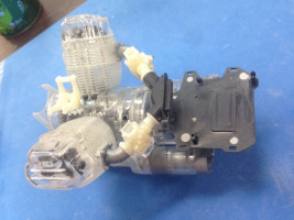
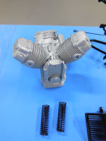
In the past several weeks I worked from Step 1 thru Step 32, which part of the Engine Assembly. Engine assembly goes to Step 40, so 8 more steps and the engine is done. Some parts were left off on purpose as they will have a different color metal paint and it is easier to paint them separate and then glue them in place instead of masking.
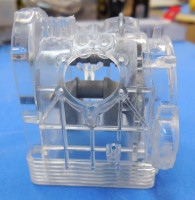
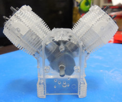
You can see the stage photos below as I went thru the steps and the pile of parts that were left out. By the way, if you plan to leave the engine transparent so you can move it or if you just want to see it move before you paint, get yourself a little tube of oil so you can lube the joints and cogs where indicated in the instructions. I grabbed the Tamiya 4WD oil. If you have a hard time finding it, any RC lubricant (not engine oil) will do.
Steps covered so far work on the following:
- Distributor Gear
- Gear Bracket
- Crankshaft
- Camshaft
- Coupling
- Pistons
- Connecting Rods
- Piston Pins and rings
- Tappets
- Cylinders
- Valves
- Cylinder Head
- Rocker-Arm Bracket
- Push Rods
- Timing Gear
- Dynamo Bracket
- Oil Pump
- Oil Filter
- Distributor
- Dynamo
- Rotor
- Pulley
- Engine side cover
- 'V' Belt
- Belt Cover
- Head Covers
- Oil-pan
- Oil-blaze tank
- Engine cabling for certain components
- Flywheel
- Clutch
- Gear box case
- Starter Motor bracket
- Gears in the Gearbox
- Gearbox
- Starter Motor
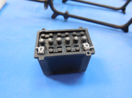
Step 33 deals with battery bed and clutch lever. I have puttied the battery bed as it had four ugly sink marks on it highly visible. And in case you are wondering, YES! the engine turns and you can see the little pistons go up and down, the crankshaft moving, etc. Quite intricate indeed but if you follow the instructions and lubricate the appropriate parts, it works great. Be careful not to clean the parts TOO MUCH, specially the cogs. If you do that you will not be able to have them touch and your engine will not turn as designed!
Once putty dried on the battery bed, it was sanded down and it was as if the sink marks were never there. Sixty five minutes later, I screwed the gearbox onto the rest of the engine. What happened on those 65 minutes, you ask? Well, let's just say that I THOUGHT I had taped the hardware box shut last time I stopped working the kit, but I was wrong. The result was 95% of the screws, bolts, etc, which once were neatly stored in its own little NUMBERED spot, now are spread in this HUGE box full of semi used plastic and rubber sprues and all the other materials I keep there (come on, it is a mammoth box, so the more you build, the more room is freed for the tools you are using!). Add to the mess curious prying eyes looking over my shoulders and poking fun at the event and you end up taking an hour+ to find the screws and bolts, sort them and placing them where they belong. But it was well worth the time as the instructions call out those hardware numbers when one is needed and the last thing you want is to go hunting for a specific bolt every time you need one! I will never forget to tape that little box again!
After attaching the gearbox, I also took the time to find and clean the hoses that are attached during this step. I dry fitted them only to make sure they were correct as I am not attaching any hoses until after I paint the engine.
Carburetors are next – two of them. Each carburetor is made up of several parts, almost like the real thing. I dried fit them to the engine and basically have a picture showing the whole unpainted assembly. This latest subassembly will be taken apart for painting as there is a rubber piece connecting the carburetors and besides, carburetors are usually made of a different material than the rest of the engine so I will paint it a different tone of metal. Worth noting here is that they have optional transparent parts for the carburetor if you are going for the "transparent build".
Next I moved on to the battery assembly which will sit on the battery bed previously assembled. You actually get to build the INSIDE of the battery which will never be seen at all! But again, I just had to do it. The whole thing goes together without any issues – as always, some amount of cleaning is necessary as there is a decent amount of flash on all parts, but nothing that a knife and sand paper cannot handle.
Next is the assembly of the rear brake mechanism. This step is so cool. Once you assemble the frame, you have to pre-attach this (which will be a true BEAR to paint!) and it actually works! I mean the foot brake will work. Kid you not. This one I have to see.
As previously announced, I had to attach the two halves of the frame and two parts that are needed to make the whole thing fit right – one of them is the rear brake contraption you just build with the preload coil. It moves like a little mini brake pedal would. All right, maybe I am over excited about the brake pedal but if you see it, you might share the excitement! Care should be taken though because the parts involved are delicate. Consider yourself warned! Also worth mentioning is the frame cleaning. Like the wheels, a fair amount of time will be spent on cleaning the frame halves. Sand, dry fit, repeat. Be careful with the attachment at the end of one of the frame halves. That is meant to attach the rear fender later on so a fair amount of weight will rest on it. I honestly don't think it will take the weight, but for me, it is a moot point anyway as it broke off during frame clean up. The funny thing is that it survived the cleanup itself, but when I glued the halves and attached the rear brake I was so concerned with attaching the preload spring right that I forgot about the fender attachment. It is held by a super thin piece of plastic and was bound to break at some point. I am happy it broke now instead of after the frame is painted. I will replace it with a metal piece which will be more suitable to the weight of the rear fender. After gluing the frame halves I sanded some more to get a good precise fit and puttied the seams as the real frame is not made of two halves!
I will mention that I have almost entirely switched to Mr. Surfacer 500 for this type of seam filling. I apply it with a tooth pick if I want a little build up, or I use a mini brush (the dental kind) if extensive smoother application is needed. I rarely use real putty from a tube these days. I find Mr.Surfacer much easier to sand off than thicker putty. I still use tube putty on occasion, but only when the gap to be filled is large as it would require too many Mr Surfacer layers/applications. And if the gap is REAL big (for example if I choose to fill up the hollow inside of a swing arm, typical in Tamiya bike kits) then I use the Tamiya Epoxy putties (green type). Milliput works great for that too.
Next we need to attach a series of small parts to the frame in preparation for the next stages of the build, but I decided to put the frame down and let it dry first. I will have to sand the frame to remove excess putty and I thought the small parts would only be in the way or break off. Patience is key!
After a few days off, the frame dried and I was able to sand off excess putty. I will only be able to tell if the putty work is perfect after I prime the frame, but at naked eye it seems fine. I proceeded to attach the support for the seat after removing excess flash and putting one of the supports as there was a huge sink mark. I did not attach the horn and the coil as they will be painted a different metal color. I now moved on to the transmission case and shaft. The shaft has a couple of tricky connections that require a flt nose small jaw pliers to make the task less frustrating. I also recommend grabbing a longer mini flat head screwdriver as the one supplied in the kit is too short to connect the exterior housing of the transmission shaft to the transmission case.
Two more steps finalize the drive train: assembling the torque link, crown gear and rear fork. Although I assembled the rear fork, I did not attach it to the frame as I find it easier to paint sub-assemblies instead of masking complete assemblies. I find masking very time consuming, so I steer away from it whenever possible! I also do not like painting every little part as I clean them for the same exact reason! I moved on to cleaning up the main stand, the rear shocks (springs to be chromed) and the side bags brackets. Next I worked on the rear fender. Amazingly enough it did not need too much clean up. License plate bracket (large sink marks on this one) along with other brackets that attach to the fender were cleaned up, but not attached at this time to ease the painting process.
I cleaned the regulator, but skipped the step that wires the tail light and rear turning signals. I consider wiring the last task for a section as masking wires is a pain and I would rather not do it. You might find that I repeat myself, but pretty much from now on everything is being cleaned up and very few things actually glued. Upper steering stem was cleaned up and assembled. There is one small ring/nut at the top that should be chrome/shiny metal. Here is a possible exception to my previous rule – in this case it might be easier to attach and paint the whole thing glossy black (body color) and then paint this small ring the correct color. I am not decided yet, but I dry fit everything because if it fits too tight, after being painted, it won't fit at all. The front forks will be functional on the finished bike so I am looking forward to finishing this tedious clean up so I can do final assemblies!
Work continued on the front fork as there are lots of brackets that need to be attached (cleaned) that will hold the front turning signals, steering damper and front fender. Also cleaned were the handlebar clamps and fuses. The fuse wire rubber cable was cleaned and set aside. Cleaning extended to the headlamp (bulbs & glass). Many other light lamps were cleaned that will be attached to the speedometer case (it is so big it looks like a dashboard!). Speedometer wires were cleaned but again not attached. Next was the handlebar itself. This one has a really bad seam line so some good time will be spent here to make sure the seam is gone without leaving the handlebar uneven. Sponge sanding is recommended here. Front turning signals got cleaned along with their lenses before moving to the rear of the bike again.
Now we are working on the tail lights and rear turning signals. The lenses and bulbs were cleaned up along with the supports. I feel appropriate to share how I clean clear parts at this point. Clear parts tend to be very brittle. I normally cut the clear part from the sprue as far away from the part as possible to avoid cracking or marring the part. When you cut the part, that spot becomes whitish and no longer very transparent and that can ruin the part. I would rather avoid dealing with fixing something like that. Once I cut it off the sprue, I use a sharp knife and little by little I cut of the excess material making sure I do not cut too much off (as there is no way to putty a clear part!). I then use a 600 sandpaper on the edges only, if needed. NOVUS is a great clear part polisher which has a 3 step process. I only use it when I am ready to attach the glass to the final part. Steps 1 and 2 are only needed if you see small scratches on the glass. Step 3 is almost a must as it brings lust to parts that have been swimming around the box throughout the build. Even in a plastic bag you won't be able to avoid some level of wear and tear on these clear parts!
Now we continue to work at the rear of the bike. I cleaned the brackets for the rear turning signals, dip-switch and license plate. Wiring of the turning signals were skipped as usual. Next on the instructions is an obscene amount of wiring! Fourteen (14) wires are attached in this step, kid you not! A few connection parts were cleaned up, but nothing was attached yet. This wiring is done all around the frame and all the electric pieces you were supposed to have connected already, so obviously it had to be skipped for now.
The instructions call for work on the wheels which if you remember, I started with the rims since it looked like quite a lengthy project. I worked some more on the wheels and decided to prime them to see how much work was left. I was delighted to see not much more had to be done. I will revisit them before sending them out to be chromed. Each wheel is made up of 4 parts and at this point I have only attached 2 of them which makes up the inner most part of the rims. There is one more piece that should be attached to each side of the rim (front and rear), but I am not sure the chroming would properly cover the part if I glue that now – I am still on the fence on that one – more on it later. I have left out the rubber valve on purpose as I can push those in at the end.
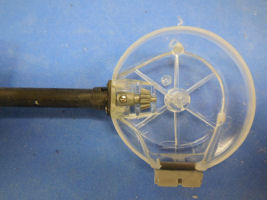
I worked next on the front brakes. You get brake shoes and they actually have springs to hold them together like the real thing. You also assemble here the brake tie rod. I cleaned and assembled the tie rod which is made up of three parts, but I did not attach it to the outside of the drum yet. I moved on to the front fender, not only cleaning up the fender itself (which did not need much cleaning), but also the brackets and reflectors that will be attached to it. I did not connect these parts to each other nor to the front fork due to future painting.
The build process switches to the rear wheel. Pin, cam, lever for the rear drum brakes are cleaned next along with rear drums and spring drive. After painted, the wheel is ready to go into the frame, but we are not there yet as nothing is painted yet!
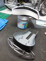
I admit that at this stage I got a little "cabin fever"! I have been cleaning plastic for almost a year now and that simply gets old as you cannot see any progress. All I have to show for right now is a bag full of cleaned parts! I decided to skip ahead and work on the larger pieces of the bike and do some priming. I assembled the tank and the side bags, primed and repeated that until I was satisfied. The tank was particularly frustrating as the middle center seam would not stay hidden. I resorted to superglue after trying Mr. Surfacer 500 three times. Since I was at it, I decided to prime all parts and subassemblies I had cleaned up so far. It was a refreshing break and allowed me to test the freshly installed paint booth in hobby room – it passed! If you can shoot two Tamiya primer cans INDOORS, without a mask (on purpose – I wanted to be able to tell the amount of vapors released) and *barely* smelt it. I guess it means it is a good booth and was properly installed as lacquer spray cans is as bad as it gets in terms of vapors. In case you are wondering, the booth I have is the Paasche 30" with 2 fans. I tried shooting the spray can in it BEFORE it was vented out as it allows for that, but it was a disaster. Maybe you can get away with non-lacquers sprays or airbrushing, but 20 seconds of spray painting was enough to fill a 800 sq room with unbearable fumes! So vent it out if at all possible!
It is worth mentioning that regardless of the final paint color I like to use the Tamiya FINE GRAY primer to see if the cleanup is ready for paint. Once cleanup gets the thumbs up, if the color to be used is red, I re-prime it in pink (or white), if it is any other color other than black or real dark something, I re-prime it in white. I find it that the primer color changes the hue of the paint so I think the extra step is well worth it – but that is my experience! I know some modelers that do not prime parts at all and claim they never had issues – to that I say "good for them".
I got a second wind after the priming session and decided to plow thru the rest of the clean up to get to the painting stage faster and finally get to build something!
Moving right along, I restarted clean-up by working on the gearbox, control lever and footboard. Maybe I mentioned this before (I cannot recall!) but rubber parts are also one of the last things to be attached, definitely after all painting is done to avoid accidently painting them. Still, I do the cleanup of the parts when it is called for and store those parts in a plastic bag as sometimes rubber parts can mar plastic parts if they are left in contact with each other for a long time. The damage can be even worse on clear parts so I make sure to keep clear, rubber and standard parts on separate bags at all times.
Many rods are included in this kit and unfortunately you have flash on all of them so extreme care is needed not only to detach them from the sprues, but to also clean them. Once a rod is broken, your only choice is to make another from plastic or metal stock using the end points from the original broken part. Trying to glue it back together proves to be useless 99.99% of the time, in my experience. In short, I try not to break them!
I went on to cleaning the gear box control unit (all the rod mechanisms), foot brake and right foot board. Next you would install the engine into the frame plus some more wiring, but I am obviously not doing that at this point. But I did prime the engine and it is worth mentioning that given that the entire engine is made up of clear parts, it is really, really difficult to see your seam work and connection points until you prime it. I have a picture shot of the primed engine showing an example spot where more clean up will be necessary. In the picture you can see how the engine cooling fins are blended together (casting issue) so it is worth taking the time to carefully remake the fins' separation as this WILL show once it is painted. This is usually the difference between a realistically looking engine and an engine that looks like just a hunk of plastic from some angles.
I cleaned up the spark plugs. At first I thought I lost one. I had that dreaded feeling of "darn it, I have to scratch built a spark plug"! But I have found that there are so many sprues on this kit that you owe it to yourself another pass thru the sprues looking for the part before you start making a new part. I also found that the sprue inventory in the beginning of the instructions booklet is very, very helpful. I found myself often referring to it to find where on the sprue the part is. That is particularly helpful if you at first cannot find the part. I also decided to cut off some sprue pieces that no longer had parts on them to lessen my pile and to encourage me – somehow a smaller pile of sprues is less daunting! I use the "3rd party triple check" method before tossing a piece of sprue in the trash – this is the method where you check twice and then give it to someone else to check it a third time. Last, but not least, regarding "sprue handling" tips for this kit, the sprues that were DE-chromed are extremely hard to read from. The numbers are still there, but the whole sprue is cream colored and mat – even with magnifying glasses sometimes it is a challenge. So I rubbed a #2 pencil on the numbers which makes the numbers stand out. Problem solved!
Turns out I did not lose a spark plug after all! I moved on to cleaning the break levers (right and left) and handlebar clamps for those, plus the rubber grips. Regarding the rubber parts, there are "P" and "Q" rubber sprues. A couple of wrong number call outs in the instructions will throw you in for a loop, but if it is "P" or "Q", just look on both sprues. I also cut them as far from the attachment point as possible and do closer clean-up on the loose part with the plastic nipper and scissors. Sometimes it is best to have a plastic nipper that you only use on rubber parts so it stays sharp and efficient on rubber.
Some cabling was skipped and I moved on to the handlebar switches (right and left). Now I embarked on a miniature cleanup! Many, many cable ends are provided, but like everything else, quite covered in flash so you need a good grip, vision and patience. Throttle control is next – again, small parts, but very complete – according to the instructions, the throttle DOES WORK. There are 2 carburetors in this engine and therefore 2 cables joined at the lever by a little contraption connected to the carburetors with return spring and all.
This bike includes a little tool box on the right side. Parts were cleaned up and are ready for paint. I moved on to the exhaust pipes. These need quite a bit of clean up as well - same deal as the handlebars – it is better done with sponges not to alter their shape. I was able to assemble the 3 piece pipes. Care should be taken as there needs to be a certain alignment (shown in the instructions) or you won't be able to install the exhaust pipe support between the right and left pipes. The individual pipe pieces were primed after clean up. Once I assembled the right and left pipes (I mean, I glued the 3 pieces for each side), I sanded the joints (which are supposed to be visible) and now they need another layer of primer to make sure they are perfect and ready for chroming. Next I cleaned the side stand and its connector. Moving on to Step 153, I cleaned the luggage rack (they call it "parcel grid" in the instructions – I love the literal translations!) but opted not to glue the two support brackets yet as I noticed that the fit on the frame is quite tight. I will glue them after the parts are chromed so I do not have to fight with it. I might change my mind on this one and glue the support brackets before chroming. I will let you know what I end up doing and the outcome.
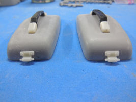
It is time to clean up the side covers. They basically hide the battery. They will be gloss black like the tank and receive the "California 850" logo. They are very visible and an eye catcher so care must be taken to make this smooth and perfect. I had to use a knife and a thin piece of sandpaper to clean the fins. I spent a good amount of time on the 2 side covers to make sure the space between the vent fins were even and straight. These are primed and ready for the gloss black paint.
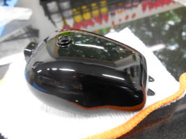
Next on the instructions is the gas tank, but I had already cleaned and glued the two halves and explained the process used so I will not repeat it here. All I need to say is that the seam is gone and the tank is primed and ready for paint. I will mention though that this bike actually has 2 fuel tanks – right and left. Therefore there are 2 fuel valves. It is unclear at this point if the real bike tank has a visible seam between them or not. I will do some research and find out as it is important. The kit provides you with an adhesive sticker to "hide" the seam line which is why I decided some research will be necessary. If the seam is supposed to be visible, all I have to do is put the sticker they provided after I paint the tank, so no big deal. The tank also has some pin striping, the Moto Guzzi logo, and a piece of chrome on each side which will be attached after the gloss black is laid down. I am pending towards painting the whole tank black and using the stickers provided for the chrome unless they are too thick and do not conform to the tank. If they turn out to be too thick, I can cut another piece out of Bare Metal Foil Chrome (or the Hasegawa Chrome sticker which is even brighter) using the provided stickers as a template. The instructions guide you thru installing the tank onto the frame. I skipped that step for now although I cleaned the fuel cap (which is also going to be chromed) and some other bits and pieces that are used to attach the tank to the frame.
I started working on the seat. The top of the seat is a nice piece of rubber but it needs to be trimmed with small sharp scissors. The bottom of the seat is plastic and needs some cleanup as well. So does the rail/handle that attaches underneath the seat but surrounds the back of the seat. That handle is very large and made up of 2 pieces. I cleaned then individually, primed to see if the mold lines were gone and then I glued the 2 parts together. In the real bike this is one piece so I decided to spend some additional time here to make them look like a single piece.
Next in line is the front windshield. You have two supports to clean and chrome. Then you have to clean the windshield itself. It comes on its own little bag which really helps keep it scratch-free. Unfortunately there are 3 rather large stubs that need to be removed. I spent quite a bit of time on this task. I had to first use pliers to get the bigger chunks off, then a sharp modeling knife and finally 600 grit sandpaper around the entire edge. Once that was done, you can scrape the excess material with the knife again. This part will need some polishing later one – I will only do that once I am ready to install it on the bike.
I can see the light at the end of the "clean up" tunnel now with only a handful of parts left. I moved to the side bags. Same comments here as I had for the tank. Each side bag is made up of two halves and needs to be glued. The seam has to be hidden so you will need to putty and sand and as you do that, you will lose the subtle texture the part has. I decided not to try to "save" the texture as it would be nearly impossible. I will replace the texture later to make it look like vinyl again. I plan to use the Model Master Vinyl Top spray and see how it looks. Or I can fabricate the texture by hand. During this step, you also clean up several buckles and fasteners that make the side bag top open and allows the top handle to be secured. The whole setup is very realistic It is quite realistic, but the parts have a lot of flash and they are very small. So it is an exercise of patience! Take your time because if you break anything, it will add a lot of time to the build to re-fabricate the pieces or you will have to close the tops and not make them functional as intended. The trickiest part in this bike that I can see is the chrome piece that needs to be installed on the bottom of the side bags. They give you a straight piece of plastic about 1.5 mm wide, 1 mm thick and about 100 mm long. It has 3 attachment points. You are supposed to *bend* that thin piece around the side bag. That means bending more than 90 degrees given the bag angle. THAT I need to see and I bet you do too! I think I will need to heat it as I do not see that part bending that far and not breaking!
At this point all parts are cleaned and accounted for and many subassemblies are glued, the biggest sub-assembly being the engine. It has taken me several months to get to this point mainly because EVERY part needs attention. There is flash and/or sink holes on literally every part. Some have more flash than others, but you will need to inspect every single part. I consider myself on the downhill side of the kit build – a very good place to be!
This installment took us to Step 178, which is the last step in the instructions. Unfortunately I will have to go thru most of the steps again after painting which is when the bike will take shape. This is my style of build mainly because I do not enjoy very much cleaning airbrushes nor do I have time for it. So I like to paint in "batch" mode. I decide what color to paint everything and then separate them in color batches to keep paint waste to a minimum. Given that I mostly use Alclad lacquer paint for metal representation, if you keep switching between colors back and forth you can burn thru those little Alclad bottles quite fast .
It is probably worth mentioning that once I get to this point on a kit where everything is cleaned and parts and subassemblies are primed, and the next step is paint, I go thru the instructions beginning to end marking the parts using different highlighter color, calling out the different paint colors I will need. I mark any parts that have a unique color with the same highlight so I know that will be part of my ‘custom batch’ (ie, the most time consuming!). I can then mount everything on BBQ skewers, alligator clips (squeezed at the end of long cocktail picks) or tooth picks and stick them on Styrofoam chunks, separating by colors. Although this step takes time, I find it overall saves me time because it avoids confusion and saves me from accidently painting the part wrong and having to redo it.
After working on a few blemishes on the engine, which required 2 more spot priming sessions, I was able to load the airbrush and lay a coat of Alclad Aluminum paint on the main engine assembly. Other colors where used on the different parts, like gunmetal, stainless steel, white aluminum, etc. I go by color and not by color name, so pick whatever you find equivalent to the real thing that makes you happy. There are many other options for metal ‘look’ paint out there. I got used to Alclad so it became my ‘go to’ paint for engines. A couple of hoses got connected at this point as well to be connected to other parts later, once the engine is installed in the frame (a little later).
I then painted all my batches. I decided at this point to switch to Alcald for the chrome parts to save on time. I had a ‘small’ roof problem in 2015 that basically rendered my hobby room unusable the entire summer as roof AND ceiling were being replaced. So for the sake of time, I decided to paint everything that would be chrome with lacquer gloss black (Tamiya TS-14), and then Alclad it all. And so I did. I also painted my ‘custom batch’ which did require a lot of airbrush cleaning but, it is what it is!
Armed with a large box of painted parts now, I went back to the assembly instructions, step by step looking for assemblies that could not be made before painting. It is very rewarding at this point as things massively shape up and progress is easily noticed as you turn the instruction booklet pages!
Assembly picked up on the engine since I was able to assemble most of it before painting it. The carburetors got connected by the rubber hoses. Note that the carburetor tops cannot be glued on yet as you need to assemble the throttle cable first, so you paint them, but separate from the carburetor base sub-assembly. The air filter is very straight forward to install on the engine bracket. Next is the battery. This bike has one of those old batteries that you fill up with distilled water every so often (remember those?). The little screw tops for the different battery elements have to be painted yellow and decaled with a very small black manufacturer logo. In my opinion, this is easier to accomplish if you attach the unpainted battery screws on the painted battery (after painting the whole battery sub-assembly body semi-gloss black). Once the screws are attached, you can brush paint the gloss yellow on the little screws until you are happy with it. Once dry, you can add the decals on the yellow caps. It looks very convincing once this is completed, and it is a shame you can see so little of it once the bike is finished. Once the battery is painted, you can screw it to the battery support in front of the air filter you previously mounted, using 2 very long metal screws provided. Now you have an engine, with battery and air filter, all painted and ready to be mounted onto the frame – later!
The next step is to attach the rear brake pull-rod to the frame. This subassembly is the same color as the frame, with the exception of the return spring. So I attached it to the frame along with a few other small bits and painted the entire frame gloss black. I really like the Tamiya Gloss Lacquer Spray cans TS-14 for gloss black. As a matter of fact, if the paint I want/need exists in a Tamiya spray can format, I use that. The only exception is if what I am painting is a second color on top of a base color – then I decant the can paint (or use another paint) and airbrush it because it comes out of the can too thick and I hate sanding that ridge that inevitably forms between colors. If you airbrush, the paint is laid down so much thinner you can barely tell the different layers (except for the color difference of course!).
The transmission case is next and the entire thing can now be assembled (although I had half of it already assembled before painting) and attached to the frame. The metal transmission case looks very nice against the gloss black frame. Next I attach the center stand and install the return spring. This stand becomes a life saver as the bike shapes up because you need to keep that frame standing on its own. That is set aside and I start next assembling the rear shocks. These look so cool once done and they actually work! I attach the rear shocks and the saddle brackets to the frame now. With an assortment of provided metal screws – this needs to be sturdy as the side bags will mount here and are removable. Make sure you do not tighten up the bracket bag release levers too much or they will not move later on in order to eject the saddle bags.
Next you attach license plate holder and other brackets to the rear fender, plus the electric wires for the rear brake lights and rear blinkers. Once this is finished, you attach the rear fender to the frame getting another neat ‘chrome-gloss back’ combination going. I will mention it here as I did not say it before. Alclad Chrome is very good. And I have used it in a lot of kits. Half way into chrome painting this kit I decided to try the SpazStixs Chrome and I have to say I am impressed. Overall, the painting process is the same as Alcad, you need to lay a very perfect gloss black layer and then you apply the chrome. The result is the same as Alclad and sometimes better. The true advantage is the price. SpazStixs is cheaper than Alclad (almost half) so you might want to experiment on your next project. Last comment on the chrome, no matter what you use, it WILL come out on your hands no matter what they say on the bottle, unless you clear coat it, in which case it will likely yellow it, or at least remove some of the shine. The chrome does not come out immediately, but as you maneuver the parts with your bare hands to get them attached, it slowly comes out here and there. So I used white thin cotton gloves when doing most of the assemblies and tried not to grab the parts too hard. At the end I had to retouch the light switch controls as it is quite tricky to get them attached to the handlebar, and the chrome got ‘worn out’!
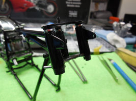
The front fork is another beautiful assembly and the forks do work after you assemble them if you use grease. I got a little tube of the Tamiya 4WD RC car grease that is available on most RC stores, but any grease will do. I had to do a lot of dry fitting here as the connection points are not a good fit anymore after being primed and painted so I little scraping off paint is needed here and there. Once the forks are attached, you work on attaching the turning signal bracket, handle bar bracket, steering damper and front fender bracket. WATCH OUT HERE! Step 68 has you cutting off these little stubs on the outside of part 208-F (blinker bracket). If you do that, you will need to fabricate a way to attach the front blinkers to the bike. DON’T cut those off! You need them!
On to the headlights, fuse and fuse wires are attached and wired thru, then light bulbs installed along with the glass and the whole thing is buttoned up with a chrome-painted finish rim and screw. Again, the small little contraption looks quite cool with the color contrasts of the different materials. You can now install the front light on the fork and tighten the screws just enough to be able to adjust the tilt afterwards. Next is the instrument panel with a lot of brush painting going on to depict the different warning lights. A couple of wires are also installed under the display before installing the display on top of the fork. Once this is attached, you can apply the speedometer decal, the speedometer needle and then glue the plastic glass (I did not have to apply any glue as the fit was perfect – if you can do the same, it is much better than using glue). Attach the handlebar now using the provided metal screws and brackets to clamp down the bars. Do NOT over tighten it. As is the case with the real thing, tighten each screw a little bit at a time in a round robin fashion – you can always tighten it more later once you decide on the best angle for the handlebar. Last finish touch at the front of the bike before heading to the rear is the front blinkers. These look so realistic! You have to assemble the chrome body, light bulb, rubber gasket and lenses – dry fit this assembly as if you get a tight fit you won’t have to use glue! Once you have the front blinkers assembled, attach them to the bracket (hopefully you did not cut off the attachment points as the instructions called for!) I keep mentioning the lack of glue being better – I truly believe it is – you have all parts painted now and the glue (any glue) will not work very well over painted parts, so it usually makes a mess, can destroy your painted part appearance and does not secure the part any better than a tight fit. But that is my opinion!
We now mount the rear blinker bracket (subassembly made of 3 parts) over the license plate support previously attached to the rear fender, attach the assembled rear blinkers and finish it up attaching the license plate. It is worth mentioning how I painted the license plate in case it gives you an idea how to do it, if you do not have a strategy for this type of painting. The license plate has raised lettering, so I spray paint it Gloss White (Tamiya lacquer spray TS-26) in several thin layers to get good edge coverage. Once dry, I brush semi-gloss back (don’t overdo it!) on a piece of foam sheet, and gently press the white license plate on the foam, letters down (like you would press a rubber stamp on an ink pad). If you press too hard, the edges of the license plate will touch the foam pad and paint the borders of the license plate and you will have to start over. Here is a situation where less is better – if the raised numbers/letters are not completely covered, you can wait for it to dry and do it again – it is best to do it 3 or 4 times than to try to get it perfect the first time and having to start over.
The next step is Step 94, which I made sure to start first thing in a ‘sit-down’ session, and made sure I was going to have several hours to complete it! It really did not take that long, but it required a lot of attention and patience – the wiring! On this step you attach 90% of the rubber wires. If you are cleaning AND attaching them, then it will take longer that it took me. I had already cleaned then with sharp scissors (don’t even bother with sanding sticks or knives) so I had to just cut off the part number and figure out where to attach and how to route it thru the frame. They give you a few rubber ties to ‘zip tie’ the cables together around the frame. I am glad they added a couple of spares ones as I broke two of them trying to tighten them (they are not very sturdy!). It looks pretty cool though once the wiring is done. I made sure to dry fit the cable attachments and routing before gluing anything. If you chose to glue the cable ends, you will need super-glue, so any corrections are very difficult. Before you commit to the overall cable routing, I advise you dry fit the tank on the frame to make sure your wire routing will allow for it to rest where it must later on.
Moving on to the wheels now, the two main pieces that make up the rims had already been glued and primed and sanded, and primed, and sanded, and primed, and sanded and primed, on and on and on! I almost gave up on this build because of those wheels. I even emailed Italeri to try to get another set of wheels to try to spoke them from scratch. But in the end, I made one more attempt to make them pass my seal of approval and after the gloss black was laid thick and the chrome hit it, I knew it was a set of ‘keepers’. I had to attach the outer rim extenders to my finished contraption, which had already been chromed as well, and finally the tires were fitted. I confess I was scared to death to ruin the chrome paint on the rims when fitting the tires. Sometimes it requires quite a struggle to mount bike tires. So I decided to run some hot water on the tires to get them more pliable and move around easier. It was a good decision. It was quite easy to mount them and the complete set looked very nice and convincing. The tire valves were a little tricky to squeeze in after the rim halves were glued, but I would not have wanted to be moving that rubber valve around and masking it thru the sanding, priming and painting stages on the rims.
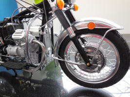
In preparation to attach the wheels, we need to mount the brake pads and mechanisms. As previously mentioned, the pads have springs and connectors that allow the brakes to actually work! It is very intricate and if lubed and mounted properly, it does work. You have to mount 2 sets of brake pads on the front wheel. Before I could mount the front wheel to the fork though, I had to attach the front fender. It is crucial to properly attach the fender trim which also serves as the connection point into the fork. The trim is attached by melting some stubs under the fender. So once you melt it, that’s it – no ‘do-overs’! Make sure you play with it a bit and find the best angle (easier said than done!). I found that the angle that would allow the fender to be bolted on to the fork was not the best angle to have the best fit on the front edge of the fender (ie, no gaps between trim and fender). So I had to compromise and produce a gap as there is no choice if you want to attach the fender later on. In hind sight, had I known the fit was going to be this poor, I could have perhaps filled the gap with some material, but at this point, with everything painted, there was no way in the world I was going to muck with it. Reflectors were also mounted by melting connection stubs. These were easy compared to the fork. There is a lot of connections made by melting plastic in this kit. The way I did that was heating up a small screwdriver tip over a flame (I used a candle in a small candle holder) and pressing it against the part to be melted. I would recommend using a (small) screwdriver with a plastic handle so it does not become too hot to hold. Front wheel is now attached and we move on to the rear wheel. The rear wheel received one set of brake pads with springs too and as you mount the wheel you have to also attach the tie rod for the rear brake mechanism (which also works!). With both wheels attached to the frame you get a glimpse of the size of this bike – my goodness! Even for a 1/6 scale, this is a big bike!
I worked on the foot plates and gearbox/foot brake levers next. This is a fast step, but you need some finesse here as you are dealing with thin plastic rods that can easily snap. If you break one, it can add hours to the build to scratch build and paint a replacement. You build these rods assemblies, but you do not attach them to the frame yet as first you need to mount the engine to the frame, and the rods would be in your way. Fitting the engine into the frame was a very fidgety step. A good dose of patience was needed here as the alignment is not perfect. Once one side is aligned, the other does not want to go where it belongs – once you align the other side, the same happens to the opposite side. You now have a painted frame with wheels and you are trying to squeeze a mammoth engine into it and bolt it on, without breaking anything… A fare share of luck and ‘gentle force’ was required! Once the engine is bolted in place, you can attach some lose wires that had nowhere to go when you ran the wires thru the frame. You can also attach the foot plates you just pre-assembled. After installing and wiring spark plugs and distributor, we move on to the handlebar and get brake levers and grips attached along with starter mechanism and its wiring. Light switches and its wiring are installed next.
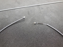
And now, we hit another phase of the build that requires a cool head and some experimentation! You need to assemble the brake and accelerator cables. They have provided a little nylon wiring extra for you to practice (and I recommend you do!). The general idea to build a cable it to cut the nylon cord to the length called for, melt a little ball at the end, run it thru one of many connectors (depends on what cable you are building), slide it into a cable guard that is very realistic metal coil, then slide one of many possible springs, another connector and you melt another little ball to hold it all together. Repeat several times and al cables are done! It is actually easier than it sounds if you follow the instructions. Remember all these cables will actually work in the bike so the sizes and gaps need to be followed. On the first cable assembled the spring provided (#13) has too large of diameter for the cable so it does not fit as it should, but you can make do by squeezing the ends a little. Once you mount the springs for the other cables, you will see how it SHOULD fit as those springs have a more adequate diameter. On Step 138, part 3, be warned that the spring # is 29, for both cables, and not 31 and 32 as called for in the instructions – there is actually no spring 31 and 32! After the cables were made we attach them to the front and rear wheel. This requires a light touch not to break anything. But the next step will definitely test your skill and patience as you attach the throttle mechanism. There are 2 accelerator cables, one for each carburetor. One end of the accelerator cable ‘duo’ attaches to the throttle mechanism which gets bolted on to the handlebars. The other end is attached to the carburetors’ tops. At this point, your engine has the carburetors mounted, but the carburetors have no tops. You thread accelerator cable thru the carb top, mount a spring in the inside and the entire contraption is bolted on the carburetors. Problem is, you need to have hands the size of a super skinny 5-year-old kid to be able to hold what you are attaching, but with the dexterity of a 30-year-old! Better yet, you need 3 hands of the same 5-year-old! So I had to call in for re-enforcement here and recruited the help of my husband to turn the screw driver while I held the bike and carburetor where I knew it could be touched. Phew…..finally they were attached and working like a charm! Yes, you can actually turn the throttle and the cables move!
We are on the downhill side of this build now. The bike is all plumbed and looks pretty majestic. We are only missing a few parts to complete the package. Tool box gets installed (sorry, no tools provided, but I bet you can make some!) along with engine protector bars and I finally arrived at the exhaust pipes. These were tricky to keep in place while the glue dried, but I was afraid of using superglue which would offer no alignment option. So I just applied the normal plastic glue and held the pipe in place for 5 minutes while staring at the walls… Same is done for the other pipe. Both pipes are then bolted to the frame which commits the fit and a bar underneath the bike hold the pipes together and aligned with the frame. Voila! Pipes are on! Next comes the neat little side stand with a return spring that actually works! This bike offers you the choice of a center stand and a side stands (as a lot of bikes do). Side covers were decaled and clear coated. I also installed the ‘parcel grid’ – this is the luggage rack, in plain English, but the literal translation of the Italian instructions adds some humor to the build!
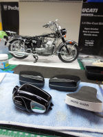
Let’s talk about the tank now. I had previously glued the two halves, puttied the seam, primed and painted it. Because of the way the tank is glued, with the lack of any support between the haves, it is not hard to make that seam reappear, even with the slightest force being applied, so needless to say, the ‘seam’ reappeared, ever so slightly, but I could see it, and it bothered me so I had to do a little sanding and lay another coat of gloss black. Once cured, I polished it to a near perfect gloss and started applying the decals. There are 3 kinds of graphics to be applied to the tank: a water slide Moto Guzzi logo, dry transfer trims and 2 self adhesive chrome decals. I wish it was all waterslide. But it isn’t so some testing had to take place to see how that multitude of graphics would react to clear coating. I applied a spare of each type of graphic to a gloss black painted spoon and followed by clear coat to see what happened. Since they did not negatively react, I proceeded to apply the graphics to the tank. It actually was easier than I had anticipated, but the thin trim dry transfer is very elastic and sticky and if you do not pay attention, you might stretch it out and end up with two different graphic shapes on the two sides of the tank! So I was constantly checking to make sure I was using the same curves and angles used on the first side. The dry transfers are forgiving to some extent – I was able to peel one off part way to realign it, but I confess I would be stretching it if I tried that again (no pun intended!). These transfers are very sticky, and some gooey glue comes out of the edges and once you lay it down, you have these little pieces of gooey material thru the entire extent of the transfer. A LOT of care should be taken if you decide to clean that up as you could easily rip the transfer – I nearly did! So be gentle and very carefully pluck the glue out. I cleaned it some but not all of it hoping that the clear coat would hide/seal it, and it did. But I think that if all of the original glue was still there, you would be able to see it after clear coating. Another tricky aspect of the tank graphics are the chrome decals provided for the sides. They are easy to apply, but the glue is not very good they lifted after some time. If I had to do it again, I would apply them the same way, but leave some pressure overnight. Mine detached from the tank a little bit as it is applied over a turn. It is disguised by the clear coat, but you can see the little gap if you turn the bike upside down. Another thing to consider here is the angle of the dry transfer trim and the perimeter of the chrome decals – the chrome decals have to be applied inside the trim so care must be taken to apply the trim so that the chrome decals fit inside the trim. All in all, the combination of mediums and the characteristics of each medium makes the decal graphics application a project within a project. I did not use the provided decal to hide the central seam of the tank as I basically puttied the seam, but if you want a quicker build, you could ignore the tank seam and later hide it with a decal. Once all graphics were applied, I clear coated in several layers and put it aside to dry.
I worked on wiring the gas lines next. The tank on the real bike is made of 2 separate sides, so you actually have 2 tanks, but from the outside it looks like one. So it has 2 fuel gauges connected by hoses and a ‘X’ connector which leads to each carburetor. It was a little tricky to attach the 2 gauges/valves to the tank because now you have a huge bike that is 95% ready and you need to turn it upside down to see the attachment point! My heart was racing with the image of this kit hitting the floor! I succeeded though – it would have been a lot easier if I had first attached the valves to the tank and then connected the wires (unlike the instructions suggest you do!). Gas cap was glued in place and then the tank was bolted onto the frame. I had to re-align some of the electric system cables so the tank would sit properly, but at the end, I got a good alignment and was able to run the long bolts thru the tank and frame and attach the nuts on the opposite side.
The bike looked amazing with the tank installed. Just seat, side bags and windshield missing now. The seat back ‘handle’ was bolted to the seat support quite easily. I painted the side wall of the seat white. At first I did not like the look, but now is has grown on me. After the paint dried I applied the Moto Guzzi logo to the back of the seat and you basically just lay the rubber seat on the seat support and slide the whole thing on the frame – there is a connection point but the fit is very minimum and lose – perhaps on purpose so you can retrofit the little optional electric engine. I don’t think Italeri released that option yet, but the original PROTAR kit had that choice and the engine goes under the seat. There are a few hardware parts that did not get used in this build because it only applies to the model with the engine. The instructions do show you how to ‘prepare’ the bike to receive the engine (which I skipped). The engine essentially makes the bike motor ‘run’ (or ‘move’). You can achieve the same moving mechanism with the provided turn knob they provide in this kit. I chose to use neither although my engine DOES move and everything else works too – I just wanted a more realistic representation of the bike instead of a transparent engine. To each its own!
I proceeded to install the brackets that hold the windshield now. Very straight forward – 4 bolts and you are done. I polished the windshield really well with NOVUS 3,2,1 steps, 3 times, to make sure the windshield was crystal clear. You then rest it on 4 protrusions on the windshield support and finish/hide the connection points by gluing the plastic chromed nuts.
Only thing missing now are the side bags. I had already joined the 2 sides for each bag and puttied the seam and primed. I later applied a new texture to make them look like vinyl again as some of the texture was removed due to necessary sanding. I used the Metal Master Car Roof Vinyl Top spray, made to represent Vinyl roofs on model cars. It worked great. My spray can was ‘white vinyl top’, which is fine, as I later painted it semi-gloss black (they make a black vinyl top spray too). They look is very convincing, even better than the original part texture, in my opinion. Three bolts are attached to the outside of the saddle bags which will be your ‘hooks’ to attach them to the bracket already on the bike. I applied the saddle bags water slide decals which were very straight forward. The many latches provided to make the saddle tops open are quite impressive. All latches had already been cleaned and chromed so I basically just had to install everything, which went on quite easily, using again the ‘melt down’ method – all connections are melted in place from the inside of the bags. Top handles were also installed/melted. Now was the part that I was sure was going to crash and burn: wrapping the chrome trim around the saddles. To my complete awe, and in my opinion defying physics (!), once I melted to place the flat part of the trim, I was able to VERY GENTLY and SLOWLY bend the trim piece around the saddle and ‘melt’ it in place. It was a miracle! Not knowing what would happen to this approach, I never even painted them chrome, but I knew I could always use Bare Metal Foil. So I did just that. It took me a couple of tries as I am not an expert ‘foiler’ but I was very pleased with the result. You can choose to install the bags on the bike or not – if you want them on, just latch the 3 connection bolts (‘hooks’) to specific places on the bike and lower the release lever. If you want them out, raise the release lever which pops them out.
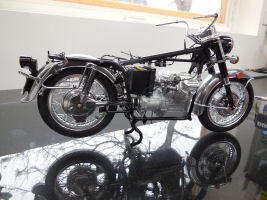
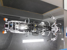
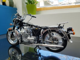
The bike is done – quite an impressive model!
Before moving into the conclusion, I would like to mention a problem I observed with the side bags. The saddle bags are droopy… I mean, once attached, they lean down at the rear, which by reference photos of the real bike, should not be like that. But if you look at the box art and pictures of the built model at the ITALERI site, it looks exactly like mine – droopy! If that bothers you, the easiest way to fix it would be to cut off the connection points for the ‘hooks’ on the saddle bags and glue them in a slightly lower place that would allow the bags to be straight. After spending almost 2 years on this kit, I ran out of ‘gas’ and decided to accept the ‘out of the box’ droopy look! Besides, I had already painted, decaled and attached the latches and trims, so the thought of butchering the bags to obtain the perfect alignment quickly faded away. Perhaps in a future lazy winter Sunday afternoon I might feel the urge to move the attachment points!
This is by far the most complex, time consuming build I have ever tackled. The kit molds show their age. This is a kit designed in the 70s, so over 30 years old. To Italeri’s credit though, they did a great job cleaning up the kit presentation with a far superior box, higher quality paper for the instructions, in a booklet format, an organized hardware parts box in its dedicated numbered slots (it is a breeze to find what you need), and also a dedicated compartment box for the engine clear parts (to keep them pristine!). The kit itself is the same produced 30+ years ago by PROTAR. So there will be a lot of cleanup, especially challenging for the small parts, and poor fit here and there. I question the decision on the dry transfer for the tank trims – perhaps a higher quality dry transfer and chrome decal would have made the graphic application ‘cleaner’. When you consider though that this kit was produced using very old technology, it is quite impressive and certainly ahead of its time. If you enjoy the subject, it is the only game in town, which can also be said about almost every motorcycle kit produced by PROTAR and I imagine now owned by ITALERI. Once the kit is built, you will be rewarded with an impressive, sizeable miniature of a classic bike and quite a conversation piece for your display cabinet!
My sincere thanks to MRC for this review sample!
