Hasegawa 1/35 P-51D Mustang Build Review
By Joe McCaslin
| Date of Review | October 2017 | Manufacturer | Hasegawa |
|---|---|---|---|
| Subject | P-51D Mustang | Scale | 1/35 |
| Kit Number | 08055 | Primary Media | Styrene |
| Pros | Popular subject | Cons | See text |
| Skill Level | Basic (out of the box) | MSRP (USD) | $47.99 |
Build Review
Scanning the stash for the next project my eyes caught two kits that I have a keen interest in building. Both are P-51D kits, one is 1/32 the other 1/24. The P-51 is an aircraft that I find interesting. I love the natural metal finish and the very sleek lines. It is also a subject that information seems to be available in great amounts. The Hasegawa 1/32 kit will be a great stepping stone for learning about the internal structures of the aircraft and give me a practice run for the larger and potentially more detailed 1/24 kit.
The only real constant in my building over the last year or so is that I am really enjoying the challenge of building cut away aircraft. This build will be no different. As I have little reference material to start with on these aircraft a search online is the first step. There are multiple sites with drawings for cut away aircraft and multiple versions of these for the Mustang. After finding a clear drawing a plan begins to form as to how to accomplish the mission. The one thing that drawings cannot do is give a real impression of the structure that will be involved. After a lengthy search a website is located that is documenting the restoration of a P-51D Racer. Now for the most part this site is not going to be accurate for the project at hand. However, there are multiple pictures showing things such as the interior bulkheads as well as some decent pictures of the wings and tail structure. It is a start.
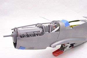
As with all cut away projects, one of the biggest questions is what detail is going to be uncovered? For this project the first step is to glue in the cockpit flooring to give its location. Using white glue this is accomplished. Using a pencil, the general area to be opened up is drawn on the interior of the fuselage side. This allows the opportunity to see just how much detail can be opened up. After some changes and adjustments out comes the Dremel and the grinding begins. Going from the interior clean-up is minimized and a much cleaner removal is accomplished. The next is the wing. Just how much detail do I want to show. Again, the temptation to show the inner workings of the wing is too much to ignore. After masking off the areas that will remain, an X-Acto with an older, broken blade is used to scribe the edges of the cut. Using the back of the blade I carefully scored the wing. In short order the wing was dissected into two parts. These are enough for now as I was unsure as to how much more is going to be exposed.
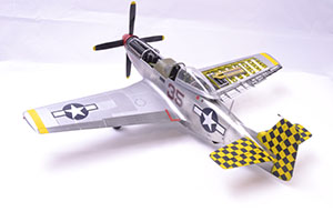
The reconstruction of the wing is the first step in the construction of this aircraft. Using the full wing and a contour gauge an outline of the wing rib that is furthest outboard is drawn on paper. Once done it is cut out and transferred to Styrene. This is just the general shape. It will be refined as the wing progresses. Using this first rib as the beginning template each rib is then traced and cut out of Styrene. This allows me some fudge factor and gives me a general shape for the other ribs. Much dry fitting is done at this stage to make sure the wing pieces will fit and have the correct shape. A couple of features of the wing are prominent. There is a fuel cell near the wing root and there is a gun bay about mid wing. After some sanding and shaping the gun bay shape is transferred to the proper frames and cut out. The fuel cell proves to be a bit of a project as first is to construct the fuel cell and then that shape needs to be carved out of the frame. This proved to be more complicated that originally believed. Once completed though more dry fitting and sanding and shaping to fine tune the details. Once completed it is time to permanently attach the frames and attach stringers. Ten frames are part of the wing. The innermost two are not attached permanently to allow ease of painting.
Painting the wing brings up a bit of debate. Research show that P-51 frames were painted in several different configurations as well as left as natural aluminium. After reading through the research Zinc Chromate Yellow is the choice with the wheel well including a combination of bare metal and ZCY. Beginning with a base coat of Rustoleum Flat Black, painting of the wing begins. The stringers are painted separately and then glued in place. Once dry the framework is masked and the intact wing panels are sprayed Testors Gloss Black. This is in preparation for a mix of Alclad and Model Masters Metalizer paints. The wing that is whole, as well as the uncut parts of the cut wing, is sprayed with Model Master Aluminium Plate with panels picked out with Alclad Dark Aluminium. Once dry I removed all masking and began to attach the pieces. Gun bay and guns are attached with minimal issue. One constant in this type of building is that if you spend a large amount of time constructing these wonderful details and you dry fit all the way through, you will in the end find that something you did that fit just beautifully during the process will not fit during final assembly. This was the case with the gun bay and the guns. Some effort was needed to get them in place without destroying the other work. It is also inevitable that you will find that you have missed something. For me this was the ammunition for the already installed guns. This was corrected by attaching the kit parts for the ammunition to a strip of styrene. This is painted Model Master Aluminium Plate with the ammunition painted with Model Master Brass.
With the wing work completed (as much as I could to this point) the interior can be started. Beginning with a contour gauge, the bulkheads are rough cut and fitted to the interior of the fuselage. Now the real fun can begin. The first major construction is the work on the flooring behind the cockpit. Again, dry fitting as construction continues, sheet styrene is cut and shaped. The process is pretty straight forward but it is important to dry fit often as this flooring will become the covering for the radiator in the lower fuselage and the tail wheel assembly. Once ready it is time for adding the detail.
I love working the interior of these builds. The research allows me the opportunity to really get into the build. As with each cut away everything I thought I knew went out the window. Research began with one of the more prominent pieces of equipment located within the fuselage, the radio equipment. The internet is a wonderful resource, but it is also a major annoyance. There are some wonderful sites that show different aspects of the different parts in beautiful detail. This is also the annoyance, while working on one set of pictures another is found that shows detail that was not shown in the first set. Deconstruction and then reconstruction occurs often. In the process a SCR 522 a radio set takes shape. There are six major components aft of the cockpit. Construction takes the form of gluing strip styrene of different sizes together in a general shape. After sanding to shape the small details are attached. Before long a rough radio set is ready to fit to the framework. The framework is not completely accurate it will however work for what I am looking for.
In the drawings I find two-cylinder shapes, these are pretty simple to shape and that is accomplished with rod and tube styrene. They are painted Alclad Airframe Aluminium. Attaching these requires a simple solution. A piece of sheet styrene is used by punching out a few holes and then trimming to shape. In the end two holders for the cylinders are ready.
Along the way a couple of sessions are dedicated to the inline fuel cell that is located to the rear of the cockpit rear bulkhead below the radio equipment. This was an interesting process and in reality, even with the cut away side it will not be seen all that well. I fashioned the fuel cell by making a frame of sheet styrene then made a covering of Milliput.
Once all the pieces and parts are ready it is time to try to mock up how to connect it all in a logical way. Sorting through the spares box as well as a box of assorted wires possible cables and wires are found. After a bit of attempts and rejections the bits are sorted and fitted. It is time to get some colour on this bit of the beast. To begin this process, the interior bulkheads are permanently attached to the flooring. All but the bulkhead to the rear of the fuel cell that is. This particular one will need to be removed to install the fuel cell. The main colours are Flat Black, Zinc Chromate Yellow, and Interior Green. Once the main base colours are applied the detail painting is accomplished. At this point, only parts that needed to be attached are glued. There is much left to do to this before all the bits can be permanently installed.
The final major sub assembly to work on is the engine and the engine compartment. A quick glance at the instructions and the sprues shows that there is a ton of detail, but it is missing a vital assembly, the engine mounts. It is time to hit the fabrication table again. The first step is to grind down all the kit moulded detail. After consulting many photos, it is determined that the kit detail on the engine is completely wrong. Once done reconstruction of some components can begin. Tubes and rods are glued in place for the ignition wiring and assorted oil, fuel, and cooling components. One of the more visible areas is actually the firewall. The oil tank as well as the tubes and such are very visible for anyone. Using a couple of clear photos details begin to take shape. It is quickly determined that there is no way possible in this scale I will be able to replicate all of the hoses, tubes, and wiring that I see. Remember this is to be a representation not a replication. Some of the more prominent visible detail is to be represented. After using Alclad paints a reasonable representation of the oil tank is glued to the firewall. Two crude representations of engine mounts are formed out of styrene strip. All the details are painted and gathered to mock up this beast. Somewhere in the back of my mind a light went off and a buzzer began to warn me of impending danger. It all fit much too easy.
Once all was done it was time to mock it up and make sure it all fit into the fuselage. Here is where the reason for the warnings about danger fit in. The engine did not fit into the compartment when the attempt to fit it into the fuselage occurred. After a bit of ranting over it I discovered the pipping that had been fashioned for oil and cooling lines were much too high on the firewall. Everything had to be removed and then reattached in the proper position. Funny thing is much of what I had done to the engine and the pipping is not visible when installed in the fuselage.
Now this is the point where all the detail for the cockpit and fuselage interior are permanently attached to the flooring. All the radio equipment is wired to give it the desired look. This is coming together pretty well even with the issues.
The time is here to assemble all the subassemblies into a whole aircraft. Beginning with the fuselage and wing problems arise immediately. The wing becomes very difficult to attach. In the end the forward scoop of the radiator is removed to allow a bit more room and then much force is used. The result is the wing goes into place with a bit of repair work needed. The fabled issues associated with this kit are now beginning to enter my thoughts. Prior to construction others had warned me of fit issues and some other problems. I chose to move forward. Scratch building the interior did help some with the issues, but others were unseen until the final attachment of the wing started. With the wing in place touch up painting is done to make sure all my heavy-handed corrections were hidden.
The top seam was one of the more pleasant areas of this part of the construction. With a bit of liquid glue, it almost disappeared. The lower seam however turned into a bit of a challenge. Then with the issue with the wing it reappeared. After the wing was in place more liquid glue was required and more putty to close the seam. More touch up with paint and she is ready for a marking session.
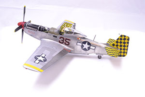
The wings were painted prior to installation onto the fuselage as previously noted. Painting of the fuselage actually began at the point where the interior areas had gotten colour. This saved me some issue as I was able to paint around the cut-out area without having to mask. The exterior became an experiment. Using Alclad Airframe Aluminium I wanted to tone down the sheen to something that looked more war weary without looking wore out. I used Gloss Grey as the base, this gave the finish a much toned-down look. Once the wings were attached touch up work and then touch up painting was a simple process.
Now this is one of the more problematic steps for this build. Starting out I noticed the decals were unusually thin for Hasegawa decals. Cool. Not going to run into the normal issue of them not settling down because of how thick they are. Ooops, spoke too soon. Starting with the larger decals I noticed the decals were not only thin but incredibly fragile. They tear with the slightest provocation. The biggest issue involved the checkerboard tail section. Placing the six large decals for the tail involved a lot of maneuvering and very careful adjusting. The last of the decals was the turning point though. When trying to apply the decal it ripped into two large sections. When trying to adjust them to fit properly the decal shattered. There was simply no way to get it back together. This was the point where I decided to take a good look at the decals as a whole. The entire tail section looked wrong. Simply put the decals were awful and did not fit as indicated in the instructions. Not good. I tried to adjust them, but each attempt ended in disaster. In the end the decals were removed and the tail was painted.
Decals were applied over several sessions to allow for overlapping. One thing that was worrying was the decals showing on the metal finish.
With all the major work done the time has come for the finishing touches. The antenna wire, the landing gear, the propeller, and other small things were now the focus.
This is not a kit that would play well with a beginning builder. There are a number of things that would hinder even someone building out of box. I believe that scratch building much of the detail as I did helped, but even then there were things that could not be avoided that caused issues. The molded-on flying surfaces as well as the incorrect and honestly weak detail are some things that I find difficult with the kit.


