Gallery Models 1/16 StuG III Ausf.G Kit Build Review
by Michael Benolkin
| Date of Review | December 2021 | Manufacturer | Gallery Models |
|---|---|---|---|
| Subject | StuG III Ausf.G | Scale | 1/16 |
| Kit Number | 64009 | Primary Media | Styrene / Photo-Etch |
| Pros | Nicely detailed kit | Cons | See text |
| Skill Level | Experienced | MSRP (USD) | $179.98 |
Build Review
For an inbox review and history reference look here.
The Gallery Models 1/16 StuG III Ausf.G assault gun kit caught me by surprise. There was no hint of the kit through the usual Trumpeter/HobbyBoss channels (who produce the Gallery Models kits) even though they’re distributed to Europe and the rest of the world in Trumpeter or HobbyBoss boxes. The scale didn’t surprise me as Trumpeter had been periodically releasing 1/16 kits over the last decade or so including their magnificent T-34/85. But kits like those are usually preceded by news and fanfare, so I wondered what was different this time. As I began researching the StuG III Ausf.G for this build, I found my answer – Das Werk (Takom) was also releasing a 1/16 StuG III Ausf.G kit at the same time. I found a video online showing the build of the Das Werk kit by Andy at Andy’s Hobbies and was struck by just how similar these two kits were. Since we’ve seen simultaneous releases of other obscure kits in the past, it seems like Trumpeter and Takom both purchased someone’s CAD designs for the StuG III Ausf.G in 1/16, and then each company put their own production details into the CAD drawings before cutting tooling. While the Takom kit has a few more details in the box, the Trumpeter kit does the surprising job of simplifying a few areas to remove some unnecessary details. Oh yes, now Heller has released its own StuG III Ausf.G kit as well. I don't know if it is their own tooling or a reboxing of either the Trumpeter or Takom tooling.
For example:
- The Takom (Das Werk) and Trumpeter (Gallery) kits both have working suspension.
- Both kits have working track, and both look and build identically. One interesting difference is that the Takom kit uses 92 tracks per side, the Trumpeter kit uses 91. Which one is correct? A reader with the Das Werk kit showed me a photo of his track parts. Not at all the same engineering as the Trumpeter and I'm glad I had the Trumpeter kit.
- Both kits have partial interior details inside the fighting compartment – the Takom kit has a floor, firewall, and radios in their kit while the Trumpeter kit does not. Given the very limited visibility into the compartment, this is not very important. Neither kit has seating, driver’s station, ammunition storage, nor ammunition. If you want a StuG III Ausf.G model with a full interior, try the MiniArt 1/35 kit and that one takes less room to park on your shelf.
- The layouts of the upper and lower hulls are nearly identical, only small details distinguish the two kits such as how the fenders mount to the hull. Both have pioneering tools on the fenders.
- Neither kit has a travel lock for the main gun. This may be a feature added to the later production StuG III Ausf.G before the Alkett factory was bombed out of operation.
- Another significant detail difference between the kits is the schurzen – the Takom kit does not have them, the Trumpeter kit provides them as dye-cut styrene parts.
Another significant difference between the kits is the price – MRC lists the Gallery Models kit with an MSRP of $193.48 and a regular price of $179.99. Street price of this kit is $139.99. Andy’s Hobbies announced the Takom kit at $99.99, but that went up to $119.99 when the first kits arrived in this country. Street price for this kit according to the few retailers that are advertising this kit is $149.99. I’m sorry, I get a headache when I see ‘new math’ at work, but bottom line is that the kits are roughly comparable as are the street prices.
So on to building this beast. The instructions have you start by adding suspension details to the lower hull and there are several steps to get this done. What is odd to me is that the most work in this model is almost a footnote here as it takes 91 track links per side, and you could almost miss this note if it weren’t for the sudden appearance of assembled track in the instruction diagrams. I don’t know about you but assembling individual track links simply reduces my will to live as many track sets out there range from boring to awful. Given that this task is the most time-consuming, I decided to deviate from the instructions and start with the track.
Each track link consists of the pad, guide tooth, and track pin. Most of the time will be spent removing the parts from the parts trees and cleaning them from tree stub remnants. Starting with the track pads, I removed 20 pads, used an X-Acto knife and hobby file to remove the tree remnants and some slight mold lines at the pin junctions. Out of morbid curiosity, I bought a set of those brass toothpicks wondering what I’d do with them some time ago, and now I find they’re ideal to align the holes joining two track pads. I carefully tapped a track pin into place with my fingertip and as I added more and more pads to the run, I fine-tuned my filing process for the next batch of track pad cleanups. Once I had assembled two tuns of 20 pads each, I laid out each run and glued the guide teeth to each pad. One note, the instructions indicate that the track pins should be inserted from the outside of the track, but the pins are actually inserted from the inside (hull side) as these pins will try to extract themselves while the vehicle is moving. There is a metal wedge welded on each side of the hull which is a ‘pin knocker’, it is out of the way of the track itself, but any pin that starts to extract itself will be knocked back into place by that wedge.
You can see here that one track run (curled into a loop) has all 91 links assembled, though I need to install the remaining guide teeth. The track in the foreground is almost complete and it too needs the guide teeth before we can check this step completed. One note as assembly of the track continues, the fit of each track link, when properly prepared, is flawless. Put two track links together and the pin literally falls into place. To get there, you need to look closely at each link as there is some mold lines on all of the mating surfaces and if you take the time to remove those mold lines, there is no work to assembling these tracks. I did not clean up the track pins until they were installed with the track links. I used a file to remove the mold stubs of the pin heads, then put the track on its side, heads down and pushed the pins in as far as they'd go, then nip any pin that sticks out on the other side. The pins will back out too easily out of the assembled track, so once I fit the track assemblies onto the completed lower hull for a test fit and verify that 91 track pads are needed on each side, I am going to carefully glue the track pin heads to the side of the track. If you're careful, the track will still articulate as before, and I'll leave one pin unglued in case I need to remove the track in the future.
Before I decided to build this kit straight out of the box, I wanted to see what I could do to correct the suspension frames for the schurzen. I removed the schurzen panels out of the packaging and was surprised that they are not photo-etch after all. This is the first time I've seen dye-cut styrene in a kit before, but that means these side skirts will be even easier to work with and won't have the weight associated with larger pieces of photo-etched metal.
So it took some time over several sessions to get these two track runs completed. Nearly 550 parts make up these tracks and once I figured out how and where to file down the mold lines on each track pad, the assembly process moved faster. Gluing the guide teeth into place is straightforward, and as I saw the track pins start to work their way out of the track assemblies while handling each run, I decided to roll up each track run, lay them on my benchtop with the track pin heads facing down, press down on the track run to firmly seat all of the pins, then flipped each run over and carefully glued all of the pin heads to each track pad. The glue did not intrude into the track joints, so the track will still fully articulate and when I install the tracks later, I will leave the final pin unglued in case the track needs to come back off again in the future.
After this photo was taken, both track runs as well as the parts trees containing the wheels and suspension were washed in Dawn dish soap, rinsed, and air dried. That will allow me to apply primer and base coat colors before assembling the lower hull.
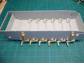
With the tracks completed, it was time to resume assembly per the instructions. Here is Step One where we mount the suspension bump stops as well as the upper shock tower mounts on both sides. The black-molded bump stops were left off at this stage as I wanted to apply the base color to the lower hull before adding the stops.
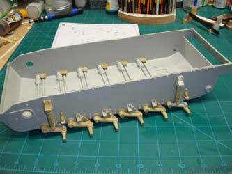
Step Two adds the torsion bar suspension to the right side of the hull along with the fore and aft shock absorbers. It was at this point that I realized that the suspension arms are set up to work, if you wish.
Here is Step Three completed and now the lower hull has its suspension system completed. Now is the time to pause for a hull base coat.
With a base coat of Panzer Yellow completed, I added the bump stops. Up until this point, I thought the black-molded parts were vinyl, but they are a styrene-based plastic and responds well to Tamiya Extra Thin Cement.
Here we are in Step Four building the road wheels and indeed the black parts are styrene, so getting the 'rubber tires' onto the steel wheels was no problem once the sprue stubs are cleaned up, but these road wheels do not go together easily, so be patient while trying to get all of the glue points inside the wheels to align and touch.
Step 4-8 are completed with the exception of the return rollers (Step 7) being mounted without the rubber tires. The return rollers are set aside for the moment.
In Step 9, all of the various wheels, mounts, brackets, etc., are installed. The real challenge in any of this are the subassemblies for the track tensioning system. The instructions indicate that the various parts that build up the tensioner on each side should be assembled prior to mounting on the lower hull. DON'T DO THAT! I did for one side and the fit was awful. Instead, parts G11 and G12 should be mounted to the hull on their respective sides, then add the various other parts and subassemblies to them. You'll find that the fit is quite nice when you're not having to align pins and holes on two sides of a hull corner at the same time.
In Step 10, you mount the distinctively dovetailed rails to the upper edges of the lower hull. These are the mounts for the fenders and upper hull assemblies.
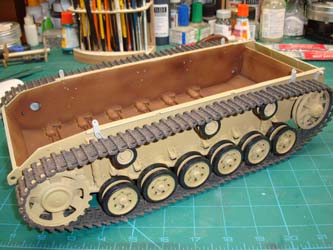
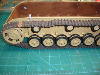
Also in Step 10 is the moment of truth - how do those hand-built track runs fit? It took a bit of fiddling to get each track run into place and the ends pinned together. I used a steel clothing pin to get the initial alignment of the track ends together, then gradually pulled the pin out as I added the kit's track pin to each track run. It fits, but it is very tight. So tight that the idler wheels and tensioners were coming back off the hull. I almost strummed the track like a guitar string to see what note could be heard, they're that tight. This takes me back to one of my earlier questions - who is right? The Das Werk kit says there are 92 track links in each run whereas the Gallery kit says 91. I build these with 91 links per run, but I'm no longer convinced.
I installed another link into this track run, making 92. You can see the track is looser, but perhaps too loose. This brings up a shortfall in this kit's design. In many armor kits on the market, the tensioner is adjustable to loosed up or tighten the track before you glue it into place. The design of the tensioner in this kit is not adjustable, but the overly tight tracks with 91 links will shear the subassembly as it is the weak link (no pun intended) in this track systems design. Some quick research online shows that the tight track look appears on new-build StuG.III vehicles, while ones that have been in action have a bit of slack in them. I'm going with 92 links in my build and nobody is going to see the track sagging across the return rollers with the schurzen installed.
Here's the last step (Step 11) for the lower hull - adding the deflector and protection for the mufflers. I left off the mufflers in this step so that I could paint them discolored and rusted before installation. That turned out to be a big mistake as the deflector frame and the photoetched screen above the mufflers now block access to the muffler assemblies. That's okay, I need to remove one of the pipes from each muffler after I finish their initial painting and rusting steps, slip the mufflers in from underneath, then reattach the pipes from above. Not elegant, but it works for me.
With the mufflers painted and installed, we begin work on the upper hull. Here's the glacis and transmission access hatches. The bit that puzzled me is that the each transmission access hatch is two doors, eight hinge parts, interior latches, etc., all for hatches that must be kept closed as there are no details to view inside. This is where Gallery (made by Trumpeter) begins to overengineer the kit.
In Steps 14-16, the focus is on the fenders. The tabs going off to either side of the fenders are part of the schurzen (side skirt) holders. The final step is to mount the fenders to the lower hull and this turned out very unsatisfactory. The resulting assembly is very flimsy and I was beginning to doubt the engineering in this kit.
Next up is the main gun as you see here, but it is not complete, just enough to see some details from hatch. The gun assembly is missing the side frames to protect the gunner and loader from the recoil as well as the basket inside the frame to catch hot spent shells. The left side is also missing the gunner's aiming controls as well, but then we know that the details provided are representative as there would also be radios, seats, ammo rack, driver's station, etc.
Here is where I lost faith in the kit's instructions. The diagrams show the assembly of the driver's vision block, starting with the interior controls to open/close the outside cover, the viewport, and then the exterior details. I tried dry-fitting the interior parts per the instructions, but this is another classic case of 'the parts go somewhere over there'. I found that building up the exterior of the vision block and armor plate first, then working inside to the cover controls, it all went together smoothly and made sense.
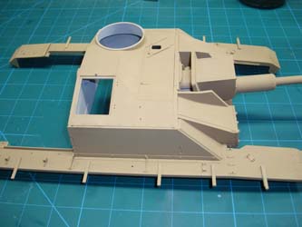
As I built up the rest of the fighting compartment cover, I decided to pause and dry-fit the cover onto the completed lower hull assembly. Nothing fit as the previously installed fenders were blocking the fighting compartment cover. After fighting with the two assemblies for a period of time and uttering a variety of colorful metaphors in several languages, I set the fighting compartment cover aside and carefully removed the fenders that had been glued into place. With the fenders set aside, the fighting compartment cover almost fits onto the hull, and with that obstruction cleared, the front of the fighting compartment cover fits snugly against the front glacis.
Flipping the fighting compartment cover over, I began dry-fitting the fenders to see if there was any pattern that matched against the cover. I took one of the fenders along with the cover and tried placing them onto the lower hull and everything lined up perfectly! I aligned both fenders to the cover and glued them into place. The fenders mounted to the fighting compartment cover creates a large 'H', and dry-fitting the H onto the lower hull not only fit nicely, it was rock-solid, not the flimsy assembly I got when following the instructions.
Work has started on the engine compartment cover and I paused again to dry-fit the engine cover to the dry-fitted fighting compartment/fenders assembly that is, in turn, dry-fitted to the lower hull. The fit is perfect. You'll note that the vehicle does not have the pioneering tools, periscopes, etc. installed at this point as I'm working to a point where the base coat can be finished and the camouflage applied before adding the tools/stowage and finally the schurzen.
The engine deck has been finished and given the base coat, and here we've also added the upper schurzen racks.
I toyed with a variety of camouflage schemes for this StuG and chose this tri-color pattern. At the moment, it only has been applied to the upper hull, but I like where this is going.
One of the obstacles at this point of the build is dealing with the smaller details. With the camo applied to the upper hull, I installed the periscopes, vision blocks, hatches, and machine gun shield before mounting the upper hull to the lower. With the hull now assembled, I extended the camouflage pattern to the rest of the hull.
The StuG III didn't have a very long lifespan. According to the German history books, Alkett was producing an impressive number of StuGs each month in 1943, but was barely keeping up with the numbers lost on the eastern front as well as losses in southern Europe. Once the vehicle arrives in theater and assigned to a crew, the StuG receives its ammo load, supplies, and a camouflage pattern. Given the wide range of patterns that have been documented in photos from the front, crews were given some lattitude on camouflage patterns based on season, availability of paints, etc. Most were sooty black in relatively short order, so you usually don't see that much rust on one of these. I did want to get the new car smell/new paint look dulled down, so I started by adding rust along the weld lines followed by a gray panel line wash. The panel line wash was also applied to all of the screw heads/bolts/rivets to help those details stand out. I fould a bottle of Kursk Mud textured paint and applied that to the track, road wheels, suspension, etc. using a big paint brush. The rest of the vehicle was given light coats of dust and soil colors to dull down the paint and then wrapped up with sooty black around the engine exhausts and the muzzle of the main gun.
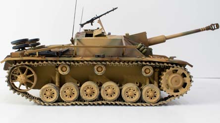
Being close to the end turned out to be an illusion somewhat. We started this project working through many small parts and that's how this project came to an end as well. Assembling, painting, and placing the pioneering tools, spare wheels, smoke dischargers, etc., took a bit of time but the effort was worth it. Once everything was in place, I airbrushed the upper hull area with Future before I applied another round of weathering, this time a wash of Burnt Sienna. The wash also dulled the gloss coat, so no further action was required.
There were a few more small assemblies called out, like a frame that is mounted over the engine deck. It appeared to be the 'towel rack' type of HF radio antenna used on command vehicles, but none of the StuGs I saw in period photos had that installed, so that was omitted. I also noted that Das Werk has a variety of engine deck load options available separately which provide ammo, fuel, food, etc, for adding additional details which would work nicely with this model as well.
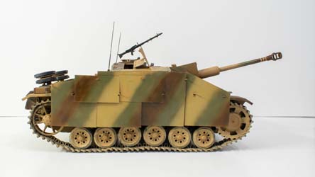
The above photos show the StuG without the schurzen installed, so here's a look at the vehicle with the schurzen in place.
This wasn't a difficult build, but it was time-consuming given all of the parts involved. I could easily spend another week or two weathering this beast to add some additional wear, but this build isn't heading to my shelf, it will wind up on display somewhere, so it is time to button this project up and move to the next. I wouldn't mind doing another build of this beast should Gallery/Trumpeter or someone else release the model with an interior.
My sincere thanks to MRC for this review sample!
