Eduard 1/48 P-39/P-400 Airacobra Quick-Build Review
By Michael Benolkin
| Date of Review | August 2006 | Manufacturer | Eduard |
|---|---|---|---|
| Subject | P-39/P-400 Airacobra (Profipack) | Scale | 1/48 |
| Kit Number | 8062 | Primary Media | Styrene, Photo-Etch |
| Pros | Beautiful detail, nice fit throughout | Cons | |
| Skill Level | Intermediate | MSRP (USD) | $29.98 |
Background
The Bell P-39 Airacobra was by all definitions a unique aircraft for its time. The standard approach to aircraft design then (and today) is to develop an airframe around a particular engine to accomplish a given set of missions. In the case of the Airacobra, Bell had been tasked to design an aircraft around a gun – American Armament’s new 37mm aerial cannon. The gun would have to shoot through the spinner to obtain the greatest accuracy and stability. In order to shoot through the spinner, you had to move the engine elsewhere, in this case behind the pilot. The propeller shaft ran under the pilot, under the gun, and into a gearbox that would turn the propeller.
The Airacobra was also the first aircraft designed with tricycle landing gear, and would definitely not be the last. As the aircraft was under development for the US Army Air Corps in 1937, a little backroom politics was going on as other manufacturers were concerned about sales of their aircraft in the face of the Airacobra. The solution was to have the Air Corps ‘improve performance’ by eliminating the supercharger, effectively limiting the performance envelope of the Airacobra below 12,000 feet.
As the Army Air Corps pressed ahead with development of the type, France placed an order for aircraft and Great Britain, also faced with German aggression from across the channel, followed suit. When France fell to Germany, the RAF started receiving those aircraft originally destined for France. At the time, the RAF desperately needed air superiority fighters, and the lack of a supercharger severely limited the capabilities of the Airacobra as an air superiority machine. As the US entered the war, the Army Air Corps pressed the RAF’s Airacobras as well as those aircraft produced for US service into combat.
As the USAAC gained combat experience in the early months of the war, they learned to play to the strengths of their aircraft. They learned the hard way that trying to fight an A6M2 or Bf 109 on equal terms in all flight conditions was a quick way to get flamed. In the Pacific, for example, aircrews learned that the P-38 was an outstanding interceptor at high altitude and could force the Zero to lower altitudes. If the P-38 followed, it too would get flamed. Instead, P-40s and P-47s could press the fight down below 10,000 feet where the P-39 reigned supreme.
As with any weapon that is not deemed ‘top of the list’, the P-39 was offered as a lend-lease solution to our allies. The Soviet Union took around half of the available Airacobras and pressed then into low-altitude service for their own layered air defense as well as for the aircraft’s excellent air-to-ground attack capabilities that would precede the arrival of the Il-2 Shturmovik in service.
The Kit
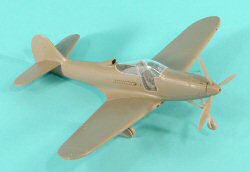
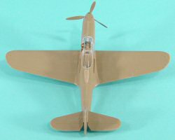
I assembled the Eduard kit according to the instructions. As with most aircraft projects, construction starts with the cockpit.
Step 1
The cockpit floor extends back to the rear of the engine compartment. The rear firewall attaches to the end of the floor. The rear cockpit bulkhead and rollover pylon mounts to the middle of the cockpit floor and the avionics shelf connects the rollover pylon to the rear engine firewall. This structure effectively ‘boxes-in’ the engine compartment should you opt to remove one or both of the engine access panels and add an aftermarket Allison engine.
The weak part of the cockpit is ironically also its strength – the instrument panel. As designed, the instrument panel sits a bit too far back so you can’t really see behind the panel from above. There is no coaming over the panel, so you should be able to see the rear of the upper instruments as well as the rear of the machine guns through the windscreen. The rudder pedals are dropped from behind the instrument panel which is way too close to the pilot’s seat. Trying to fly in this cockpit would feel like trying to drive a kid’s go-cart – when you put your feet on the pedals, your knees are right under your chin!
On the other hand, the instrument panel is the most prominent feature in this cockpit. Eduard provides a two-part color photo-etched panel that renders the instrument faces and warning pledurds in full view. This color photo-etch approach replaces the previous printed instrument faces on acetate. While the acetate approach worked, the color photo-etch looks nicer. The pilot’s seat also has color photo-etched seat belts and shoulder harnesses provided.The nosegear well is added to the front of the cockpit assembly. This will take a bit of dry-fitting and patience to get everything aligned before cementing everything in place. Once I’ve glued everything together, I clamp the drying cockpit/nosegear well assembly inside the fuselage halves so that the dry with the floor and bulkheads in proper alignment.
Step 2
The throttle quadrant is installed in the left fuselage half, then the cockpit/nosegear assembly is cemented into place. I clamp the fuselage halves back together and set the assembly aside to dry.
Step 3
The wings go together without problem. There are a few radiator doors that are represented in photo-etch that are skipped for this quick-build.
The wings mount to the fuselage okay, but there is a slight gap at the wing root/fuselage join and the dihedral of the wing is a bit flat. This is quickly overcome by running some liquid cement along the wing/fuselage joint and putting a rubber band from one wingtip over the cockpit to the other wingtip. I set this aside to dry. When I removed the rubber band, there was no gap at the wing root and the dihedral was just fine.
The horizontal stabs also install without problems.
Step 4
The photo-etched radiator grilles and flaps are omitted for this build.
Step 5
The landing gear is nicely rendered and you have your choice of rounded or weighted wheels. Many of the smaller parts were omitted as were the external stores.
Step 6
The nose gear goes on as smooth as the mains, the small parts were omitted here as well.
Step 7
The canopy and car doors install and the fit is nice!
Step 8
The prop is assembled and installed. The wing guns and pitot tube go on at this stage but were omitted for this quick build. For some interesting reason there is a single three-bladed prop provided in this kit and two different styles of four-bladed prop. Are there P-63s on the horizon?
Conclusions
This kit definitely is a nice build and when you factor in the photo-etched details, the results will be stunning. Since the kit does rely heavily on photo-etch, this kit isn't recommended for the novice or less-experienced modeler.


