DML 1/72 A-25A-5-CS Shrike Build Review
By Sundiata Cowels
| Date of Review | January 2014 | Manufacturer | DML |
|---|---|---|---|
| Subject | A-25A-5-CS Shrike | Scale | 1/72 |
| Kit Number | 5115 | Primary Media | Styrene, Photo-Etch |
| Pros | Very detailed | Cons | Confusing instructions |
| Skill Level | Experienced | MSRP (USD) | $43.95 |
Build Review
Dragon Models' Golden Wings Series release of the A-25A-5-CS Shrike is certainly one of the most intricate kits I have ever had the pleasure of building in 1/72 scale. For reference I chose to utilize the 1966 edition of Profile Publications' "The Curtiss SB2C-1 Helldiver" No.124 by Harold Andrews. Since this is to be a quick build, I will be using Testors Non-toxic glue (no. 3521), an Excel hobby knife with X-acto blade 11 installed, tweezers, toothpicks (for applying glue), clothespins, and a large magnifying glass. I will not be using the photo-etched parts in this build nor will I be painting it.
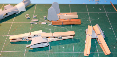
[Step 1] My journey begins with the choice of building the rear collapsible gunner window in either the up or down position. I've decided that I want to show off the Shrike's twin .30 cal machine guns, so I opted to build the window section down (Option B in the instructions). Parts C53 (base of the aircraft tail fin) and E5 (the rear top window) go together without a hitch. The collapsible walls are assembled out of two parts each and then are to be glued to the bottom of the aforementioned parts C53 + E5 unit. The trouble here is that the collapsible walls in the instructions are drawn with alignment pins which are not present on the actual kit parts. Examine these parts thoroughly before you apply the glue!
At this point, I decided not to mate the C53+E5 assembly with the collapsed walls (parts C52+C49 and C51+C50 respectively) because I fear that since they will have to fit onto/into the assembly fuselage, I'd rather leave myself some wiggle room in terms of fitting it in place.
[Step 2] In the next step, the instructions guide me in building the tail gunner platform station (Assembly C). The drawing of the platform is shown in an off angle- make sure of your alignment before you glue on the side wall framework.
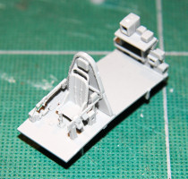
[Step 3] When you get to the cockpit, things start to get confusing. Part C14, appears to be a lever, and is labeled indirectly via another part (C7). It is lost in the line drawing of part C12 (right hand sidewall instruments). This piece is so fragile that not only did it pop up and away from my table once I cut it from the sprue, but when I finally recovered it a day later, I unfortunately cut it in half while trimming it. Arrgh. I would suggest, to build and install subassembly F (pilot seat with photo-etched seat belts) first, before adding the levers and sidewall gear.
[Step 4] After your cockpit has dried, turn it over and start work on the bomb bay. The bombs come in three parts, and you'll need clothespins to clamp the bomb tailfins firmly in place. The bomb crutch requires delicate handling when you remove it from the sprue tree.
The bombs have shallow indentations for the bomb crutch mounts- the smallest dab of cement (applied by a micro applicator or toothpick) should do the trick. I let it dry overnight before handling it again.
[Step 5] Flipping the cockpit right side up once again, in step 5 you are asked to install the rear cockpit pilot bulkhead and, oddly enough, the pilot's instrument panel (A11) in what confusingly looks like onto the cockpit floor! Ignore this and install the instrument panel as per the illustration in Step 6 which shows it in place under the coaming on the starboard fuselage half.
At this point the instruction artist would have you install the pilot seat… onto what appears to be the cockpit floor surface in front of the instrument panel! Gosh!
[Step 6] Step 6 is a massive compilation of three sub-assemblies ending with the joining of the two fuselage halves. This is where things get interesting.
Sub-assembly D builds the dual .30 cal gunner's mount (or single .50 cal) out of ten very fragile parts. I definitely would advise using a stand with alligator clips to hold the pieces as you cement them together.
Construction came to a halt when I was unable to discern how the gunner's ring seat was to fit inside of the gunner's platform. The instructions inform the modeler to "drop the seat in", but as to exactly how, was too vague. I elected to leave the seat out and try to fit it in later.
After installing the propeller shaft housing, cockpit, gunner's bay and rear gunner deck into the starboard side fuselage I then cemented the fuselage parts together. The ventral exhaust port box (C34) was missing from the kit.
[Step 7] The engine sub-assembly for drawing has parts C38 and C39 reversed; luckily I caught this error before the glue dried and repositioned them in proper alignment.
While the fuselage dries, I moved on to putting together the tail planes and the wings.
The inner wing upper halves, B9(B10), are cemented to the lower wing halves B5(B6).
Mislabeled parts G29 and G28 (they should actually be parts D29 and D28) are wing half supports that fill in the space that would be occupied if the wings were displayed folded.
After the glue dried, I re-examined the fuselage and found a gap underneath; I would suggest using a table mounted vise to secure a tighter bond rather than the tape and rubber band combo I utilized. The gap should be easy to fill with a bit of putty.
Continuing with the assembly, I mounted the inner wing halves to the fuselage and added the engine block to the front.
In hindsight, I think I should have actually followed the instructions for once; Dragon illustrates that the wings should be assembled all at once as single wing units per side and THEN mounted to the fuselage. I'm not sure if the gaps are due to my backwards approach or the kit's engineering.
Construction once again comes to a halt when I dry fit the gunner's rear collapsible roof onto the fuselage- the alignment pins do not fit into the guide slots. At this point I think my only option is to cut off the alignment pins, break apart the roof assembly and then re-attach it, piece by piece to get the proper positioning. Yes folks, this piece is a bit of a pain…
The landing gear sub-assembly of Step 7 is a challenge due to the instructions once again and for the first time, the engineering of the kit parts. The Dragon instructions asks the modeler to assemble the entire landing gear arrangement in one go, and then just "drop and glue" it into place on the wing. Fearing a repeat of bomber/gunner collapsible roof and twin .30 cal sub-assemblies as I have described earlier, I decided once again to put this together in a more logical sequence.
The tire halves are incorrectly listed as D8(D8) and G4(G4). If you follow the instructions as is, you would be combining two different model inner wheel hubs together. Substitute inner wheel half D9 for D8.
Next, insert the main gear struts (Parts D21 and D20) into the alignment slots into their respective boxed in wheel wells. The fit here is a bit wobbly, and even after letting it dry overnight, inverted and leveled, before continuing my assembly, I noticed the next day that the struts still wound up on a slight angle. I would advise shaving off a little of the alignment pins on the struts to get them on a more perpendicular angle to the ground.
As per instructions, I then mated the gear support brace (Parts D3 and D2 respectively) to the main struts. There are no alignment pins for this step and I had trouble determining just what was expected- if I followed the drawing to the "letter", the upper half of the support brace would be below the actual wing; making its purpose null and void. I decided to cement the upper part of the brace into the wing first (after finding a small slot not mentioned in the drawing) and then angle the lower half onto the actual strut.
Landing bay wheel covers D27(D26) are then glued to main strut cover doors D25(D24). Thankfully these fit together like a glove.
With a minimum of fuss, the wheel fit onto the main gear hub and the doors fit onto the main gear. Whew!
Still puttering along on Step 7 I decided to add the dive brakes/flaps onto the wings. Once again, the poor illustrations made what could have been a simple installation into a frustrating exercise.
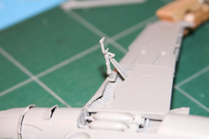
Dragon gives you the choice of positioning the brakes open or closed. I opted to have them closed. The directions show the brakes glued together and cemented to the rear of the wing. Unfortunately it is not that simple. I inferred that all I had to do was cement the upper brake halves (F3 and F10) to their corresponding lower parts (F5 and F8). What I quickly realized was that the halves are not matching pairs- the upper half is shorter than the lower. Confusion continued as I could not determine if the dive brakes were to fit within the gap of the actual wing or if they were to fit flush along the edge. I decided to fit them flush along the wing.
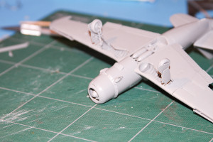
While they brakes dried I moved on to the under fuselage engine exhaust pipes (Parts C3, C54 and C21). This fit together without incident but it would have been helpful to know just how far in the pipe needed to be inserted into the fuselage bulge.
Jumping out of order once again, and taking advantage of the exposed bomb bay, I added the bomb bay doors, minus their actuator hinges; these parts were too delicate to be removed from the parts tree. I would suggest utilizing a very hot knife to do this in order to mitigate the risk of breaking the pieces like I wound up doing.
The bomb bay doors are (surprise, surprise) labeled incorrectly in the directions; Part A7 should be swapped for Part A8 in order to fit correctly onto the ventral part of the fuselage.
After the bomb bay doors dried, I then moved on to the under-wing weapon mounting stations [Step 10]. Each wing mount is comprised of three very small pieces which, thankfully assembled without major incident.
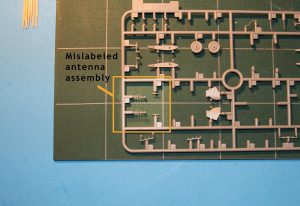
The under-wing antennas were problematic due to poor instructions and miniscule connection points. Directions call-out part D18 which represents the antenna itself, but the pole that it is connected to, allowing it to stand off from beneath the wing, has no identifier. Using an educated guess I was able to deduce that the unnamed piece was actually part D19. My deduction was based on a good five minute scan with my magnifying glass that resulted in me noticing an ever so small alignment socket and pin on each corresponding part. With my difficulty with removing small parts from the sprue tree, I decided to remove the poles first and cement them to the antennas, letting the assembly dry overnight before cutting the entire unit from the tree. This worked out well.
The remainder of the dive brakes and flaps were added next as per Step 10. The fit of the upper dive flap/brake on the starboard folding wing was so inaccurate, that I had to cut off the bottom corner of the flap in order for it to align correctly.
In Step 11, photo-etched flap covers would have been used to cover over the dive brakes had I been utilizing them in this build.
I added the propeller next, having had already pre-assembled it on the sprue tree some time before. With a little finagling, it was able to align it into the shallow engine hub socket receptacle.
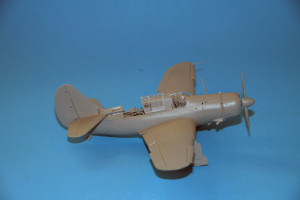
At this point it started to look like a Shrike… after a fashion. I slingshot my efforts back to Step 7 and using some multi-purpose white glue attached the front windshield and the pilots canopy.
The molding of cockpit and gunner clear parts is not only very fragile but also surprisingly almost a size too small. As such, contrary to the instructions, you really don't have the option of modeling the canopy open- the "glass" is not large enough to fit around the fuselage frame and line up with the appropriate grooves. Attempting to force them down into place using binding or pressure only causes them to fracture under the stress. For this build I have not cemented the rear gunner window in place so that you can see how high it "rides."
Which leads me to the part I've been dreading since this build began- the final assembly of the gunner's machine gun station.
Having put this off until now, I still could not see how I was supposed to confidently mount the turret ring and seat into place without any kind of alignment pin or guide.
I decided to cement the sides and bottom support rod of the turret, fit it into the fuselage as close to the sidewalls as possible, invert the whole plane and wait until morning.
It worked, after a fashion, and the next day after I glued the twin .30 cal guns into place, I tackled the next unsolved mystery as to how to build the rear collapsible gunner roof section. After cutting my original assembly apart and re-cementing it at what I thought was the proper angle, the unit still didn't fit as advertised and I ended up with what looks like a roof stuck between the up and down position. Not cool.
Main antenna and a pitot tube later, the "Beast" was complete.
DML is to be commended for making a very detailed kit of this variant of the Helldiver and in patient hands and the proper research materials, this could be made into a fine model.
But the poor instructions, fragile clear parts, un-necessarily small sub-assemblies for pieces that could have been molded as one piece, and the lack of proper alignment holes or corresponding pieces makes this model suited only for experienced builders.
My sincere thanks to DML for this review kit!


