Classic Airframes 1/48 Ro 37 Quick Build Review
By Michael Benolkin
| Date of Review | October 2004 | Manufacturer | Classic Airframes |
|---|---|---|---|
| Subject | IMAM Ro 37 | Scale | 1/48 |
| Kit Number | 0468 | Primary Media | Styrene, Resin, Photo-Etch |
| Pros | Exquisite windows fit, nice detailing | Cons | Nose fit |
| Skill Level | Intermediate | MSRP (USD) | Out of Production |
Background
For a look at the Ro 37's background and at this kit straight out of the box, check out the review
published earlier on Cybermodeler.
This is a quick-build review, meaning that assembly is straight out of the box with no fillers used to close any gaps, and no painting of the resulting model to show any problems that might have arisen in assembly.
What you see is the result of the fit of the kit as designed, with a minimum of filing and/or sanding used to remove ejector pin marks, molding tabs, etc. Except as required for photo-etch assembly, all of the kit assembly was done using Testors Liquid Cement.
Assembly

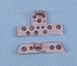
In Step One, the assembly process begins with the front and rear cockpit instrument panels. These are nicely done with a photo-etched panel face, acetate instrument faces and a styrene backing, all laminated together. A photo-etched compass mount is attached to each of the instrument panels. In Step Two I elected to skip this step as you assemble the front and rear cockpit parachute packs and harnesses. The parachute pack and all of the restraints are photo-etched parts and nicely done.

With Steps Three and Four the nose is cut away to make way for the inline engine cowling. I used my trusty X-Acto mitre box and saw to get the cuts square and true. When I built the Classic Airframes Hudson kit a few years ago, I was amazed at how well the windows fit and wondered if this kit would be as precise. It didn't take long to find out, one window went into place perfectly in the right fuselage and only a hint of flash needed trimming to get the left fuselage window into place. Nice! With the windows installed, it is time for the tubular fuselage frame sections to go into place.
Step Five is the most complex in the build, so take this one slow and do lots of dry-fitting to understand how it all goes together. This is where the cockpits are assembled (no problems here) and the resulting assemblies go inside the fuselages as they are brought together. The rear cockpit floor goes into the bottom of the fuselage, trapped under the tubular frames in each fuselage half. The front cockpit floor mounts higher in the mid-fuselage as indicated by the instructions, the slots in the floor sides align with the tubular frame. Getting the two cockpit floors into position while assembling the fuselage halves just takes a little care and patience. Actually, the biggest challenge for me was installing the front cockpit instrument panel.
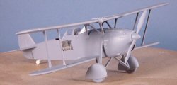
In Step Six we install the lower wing and remaining windows. The fit of the bottom lower wing half to the fuselage is almost perfect. So much so that the lower window only needed a little 'tweaking' to get a perfect, gapless fit. I installed the upper halves of the lower wing and everything went together gap-free. The upper observation window that mounts between the cockpit openings also slips in nicely, but the contour of this window extends slightly above the cockpit bows immediately in front and behind the window. This can be adjusted with a styrene shim in each of these bows to get everything aligned. You can see in the photo how well everything is going together.
With Step Seven, it is time to install the upper wing. I pulled out my trusty wing jig and got the model squared up and level. I installed the upper wing according to instructions, and while this is drying, I used the jig to install the horizontal stabilizers as per Step Eight.
Step Nine assembles the replacement inline engine cowling and propeller, and attaches the result to the fuselage. This was really the only fit problem in the kit and even this was minor. With the nose aligned to the fuselage top and sides, there is a step between the bottom of the nose and the fuselage bottom. While it is visible now, the problem is hidden when the landing gear is installed.
In Steps Ten through Twelve we assemble the landing gear. In Step Ten, you chose between the nicely done photo-etched spoked wheels or wheel pants. For expediency, I opted for the wheel pants, but you'll want to check your references to see if your subject had these installed at the point of time you are modeling. The main landing gear struts (B9 & B16) have recess points provided in the fuselage for ease of installation. I found that the lower nose step I mentioned above provided a solid mechanical point for strut supports B10 & B15.
Conclusions
This kit went together very smoothly. As you can see with all of the photos, there weren't any glaring problems with assembly, and I still am amazed at just how well the windows of this kit go in perfectly with so little effort. I assembled the kit per the instructions and because no painting was done, I was able to complete this project in about six hours, which includes frequent breaks to allow the liquid cement to dry. You can see in the photos that filler isn't really required. Overall this kit is very well designed and should be an easy project for the skilled multimedia modeler.
My sincere thanks to Classic Airframes for this review sample!


