Anigrand Craftswork 1/72 Lockheed C-141B Starlifter Build Review
By Fotios Rouch
| Date of Review | November 2008 | Manufacturer | Anigrand Craftswork |
|---|---|---|---|
| Subject | Lockheed C-141B Starlifter | Scale | 1/72 |
| Kit Number | 2082 | Primary Media | Resin |
| Pros | Nice detail | Cons | Canopy fit |
| Skill Level | Intermediate | MSRP (USD) | $196.00 |
The Build
It is amazing how some aircraft are so neglected by the hobby industry. The Starlifter seems to be one of them. There was a nice 1/72nd scale vacuform kit from Nova which I had bought new in 1986 but I never built it and eventually sold it to the late Al Superczynski. Then Combat Models made something in the same scale and that was it.
I was pleasantly surprised when Nostalgic Plastic announced that Anigrand was going to make the Starlifter for them in both the C-141A and C-141B variants.
Upon opening the box the modeler will be surprised with the size of the resin parts. This is one big model! The fuselage is offered in four parts due to the difficulty of casting at such lengths.
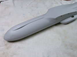
The modeler can approach the fuselage assembly in two ways. Assemble the front fuselage halves and then the rear fuselage and then merge the two assemblies. After taping the fuselage parts and trying to dry fit them all together I decided to go the other way. I took my time and assembled separately the left and the right sides. This way I achieved a near perfect fit between the front and rear fuselage halves. I cut off the locating pins because in my example they did no allow the parts to line up right.
Once the fuselage halves were complete I merged them together starting super gluing from the front and progressively moving to the rear of the fuselage. There is no way to glue such long parts in one shot! Working slowly and a bit at a time allowed me to get the alignment as good as possible and also to squeeze the resin here and there to make sure that it did not leave any big steps or gaps along the way. Still, some 3M putty was needed here and there.
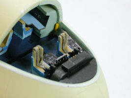
I decided that there was no need to build up the interior beforehand since there was so much room to work on it later. The first priority was to have the parts line up and also get a good joint for the cockpit floor.
It is pretty difficult apparently to get huge resin parts to come out perfectly with no pinholes or bubbles. My example has some imperfections around the front of the fuselage where the cockpit transparency would attach. It is very easy to fix such imperfections although I do wish that they would not be there in the first place.
What I did was to open up the resin bubbles until the appropriate diameter of styrene rod would fit perfectly in the hole. I super glued the styrene in the resin, sanded it to match the fuselage curvature or sanded flat, whichever the case might be and this is all it takes.
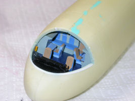
Anigrand has got much better with casting clear resin. My clear canopy transparency was much better than what included in their C-17 kit. The only problem is that it shrunk in curing and it was undersized leaving gaps all around the fuselage. I was trying to figure out how to fix that because there is no way I was going to master a new one! I noticed that if I would put some styrene stock to raise the clear resin part, it would fit pretty well. So out came the styrene and after I traced the canopy outline, I carefully scored it with a fresh X-Acto and cut out a template to essentially create a step for the clear part to be elevated to the right level. Lots of sanding and test fitting took place until I was satisfied. The clear part was taped in place and was used to contour the styrene for a flash fit all around. After that the clear part was put away and work started on the cockpit parts.
Now why is it that we modelers don't leave things well enough alone even when we fully well know that a certain assembly will be invisible to all is beyond me. And to prove the point I went on to rearrange the interior to the configuration that better matches the photos included in the CD that Nostalgic Plastic is offering inside their kits. I added a few things here and there, like tables for the flight engineer and navigator, seat belts, extra seat arrangements on top of the rear bunk, oxygen tanks, throttles, steering yoke, and changed a bit the instrument panel. I will be darned if anything shows after the model is completed but it makes me feel good about the job.
When the cockpit subassemblies were all done I inserted them in the cockpit cavity starting from the back and moving forward. It all looked good in the end and last step was to super glue the Futured transparency. I covered the windows with Parafilm and with an X-Acto and an old Dymo tape I cut around the windows following the finely engraved window outlines.
The landing gear sponsons were attached to the fuselage and the fit was actually pretty good.
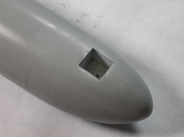
I then sprayed the first coat of automotive primer to reveal all the assembly imperfections and the pinholes that were present around the fuselage. The primer is naturally a bit rough and Acryl Blue loves to stick to it and fill the pinholes. Some time was spent on this process because it is much easier to get all that take care off when the wings are off and it is much easier to flip and turn the fuselage. The two resin parts that constitute the refueling receptacle on top of the fuselage were then attached.
Once the pinholes were covered and the Acryl Blue was sanded down, I applied one more coat of primer. I was satisfied to see that the imperfections were gone.
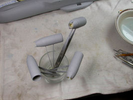
Building the jet pods was pretty straight forward as far as construction goes. I tried to match the parts with each other by test fitting just to see what pieces would pair up the best way. This helped lessen the sanding and filling part a bit. Pinholes were filled and the jet pods were sanded smooth with flexi-pads to preserve their cylindrical shapes. Things looked good but the eye often deceives, so out came the automotive primer and sure enough more Acryl Blue was necessary to fix surface and assembly imperfections. When all looked good enough I used one more coat of primer and left the pods alone for the night. Rescribing and more sanding and polishing would follow later. The pods were then merged with their respective pylons using cyanoacrylate glue and accelerator. The fit of the pylons to the pods was not very bad and the small gaps were hidden with a thick coat of hand brushed Mr Primer 500.
The wings came together with no big problems other than the expected clean up of the joints prior to gluing and a light sanding of the mating surfaces to improve fit and adhesion. The wings are long and a bit heavy so I decided to remove the resin locating stubs and replace them with metal rods. The rods were not placed in the exact position were the resin locating stubs were.
The fit of the wings to the fuselage was not all that great and lots of fine tuning was necessary. The metal rods that support the wings were moved around a bit until I managed to get the best fit I could based on the different contours of the fuselage the wing base. I had more problems in matching fuselage to wing with the port side and a bit less with the starboard. The starboard wing had a different problem and that was a sunken area toward the middle top. Acryl Blue again was applied with a fine spatula.
The model was then sprayed again with automotive primer and rescribed because all this messing around ruined a bunch of the panel lines on the top of the wings and the fuselage.
I then flipped the model over and worked a bit on the front wheel well. Careful on this one as the instructions would have you cut the resin wheel well doors in four pieces, two to cover the front of the well (correct) and two for the aft portion of the front wheel well (wrong). The Starlifter had a solid aft wheel well cover that would go out and over the fuselage to make room for the extended landing gear. I made my own landing gear cover and scratch built the attachment gear since none is provided in the kit.
One thing that maker of this model missed or elected to skip was the inclusion of the APU in the front area of the port sponson. I first scribed the oval area of the APU then drilled through and then I used fine plastic sheet to cut out a rectangular area to represent the polished metal panel that surrounds the APU. The next thing I need to do is to fabricate the APU hose and attach it inside the sponson.
One other thing that I did not like in the kit was the look of the main landing gear wheels. The maker did something simple and it might be ok since they are not very visible on the completed model but it bothered me just the same since they look nothing like the real thing. I felt that based on the photos included in the CD that came with the model that the wheels that come with the C-135 kits look good although even though maybe a bit larger in diameter. I went with it and the results were more pleasing to my eyes.
Another thing I did was drill out some lightening holes to the soft metal landing gear included to help with the look but I know that they are circular and the real ones were oval but there is only so much time I was going to invest in this specific effort.
The other thing that has been bugging me about the model is the lack of detail with the jet pod intakes. Firstly the fan face is too far forward. Then the fan blade bullet is not long enough. Lastly no stator blades are included. The stator blades are a very important characteristic of the Starlifter engines and there is no way anyone can miss it if they have ever seen a picture of a C-141. My guess is that the maker did not have an easy way to reproduce them so he skipped them and modified the depth of the intakes instead. In any case, I decided to make my own and used styrene strip to create them. Long, tedious and annoying process because the bullet is not as long as it should be to accommodate the stator blades. I compromise as best as I could. I feel that the result is convincing after painting the fan blades silver and the stator blades steel color with a rustic bronze color for the intake lip.
I just could not wait to see how the monster would look in its Air Mobility Command Gray! I bought two jars of the Testors paint and went for it. One jar was gone to just cover the model and I am working with the second one for small fixes and additional work later.
The project is getting closer and now that I have painted the model I am running a pencil over the panel lines so I make sure they are well defined and then I will run a very fine mist of AMC gray over them to dull the pencil lead down and start with weathering and other details.
The next big work item was attaching the landing gear. The front landing gear fits very securely and gives the proper stance for a Starlifter on the ground. The main landing gear does not have a positive lock in the resin sponson and needs to be attached with care. Not only that but care has to be taken so that the main landing gear is symmetrical and that it allows the model to sit on all ten wheels.
I used the black cyanoacrylate glue which I think contains rubber and it allows for very strong bonds. I had the model upside down and waited until it was almost cured. I then flipped the model and as the main wheels touched the work surface I made some fine adjustments and left the glue to dry with the weight of the model on the joints. One thing I could have done was to shorten the length of the main landing gear. I it is, the model sits too high. Since this model will be suspended from the ceiling I am fine with the length of the main landing gear struts which look fine in length for a plane in the air.
With the model was upside down, I added a tube to represent the APU hose in the port side and also added clear acetate over the two hole under the wings for the landing lights. A drop of Future over each hole completed the effect. I scratchbuilt the front landing gear hatch panel and built the retracting mechanism from styrene sprue.
After the underside work was completed I flipped the model on its landing gear an starting adding details.
All the antennas were made from styrene and there are plenty of them. Look at your reference photos because the antennas and their positions changed from plane to plane, era and mission. The side windows were painted gloss black.
The rear McChord logo was painted with green (Airfix emerald green, willow green, blue and yellow) and decal stripes were added on top and bottom with the McChord provided logo added in the end. The decals adhered OK but be careful and make sure you have a very glossy surface because they will silver.
The wingtip navigation lights were done by first painting the tips with high gloss silver and then with Tamiya clear red and blue.
Weathering was done with pastels and a coat of Testors mate varnish was sprayed in the end. The intake covers were done with aluminum foil painted red.
Conclusions
Overall this is an OK representation of the Starlifter. I wish the maker had paid more attention to detail and had gotten the tail are better, the sponsons more detailed, the clear canopy better sized, etc. Having said that, it is very unlikely we will ever see another 1/72nd Starlifter from another company so I am glad that we had this model come along.
My sincere thanks to Nostalgic Plastic for this review sample!
