Amodel 1/72 Myasischev 3MD Bison Build Review
By Fotios Rouch
| Date of Review | May 2018 | Manufacturer | Amodel |
|---|---|---|---|
| Subject | Myasischev 3MD Bison | Scale | 1/72 |
| Kit Number | 72014 | Primary Media | Styrene, Fiberglass |
| Pros | Nice detailing | Cons | See text |
| Skill Level | Intermediate | MSRP (USD) | $169.00 |
Build Review
The 3MD variant offered by Amodel is the only one that they provided dropped flapsas an option. This makes the model especially appealing to me since I am planning to build it with the landing gear extended. You can find an in box review of the kit here and inbox reviews of the other siblings here and here.
Since Amodel either cannot make big molds or they do not find it cost effective they provide all the big parts in fiberglass resin. This material needs a little more work as it is harder than polyurethane resin for example.
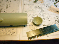
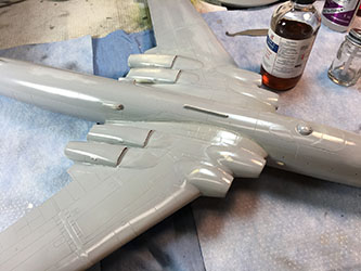
The work began with that big fuselage. It was washed and then all the joints were sanded down with various grades of sand paper. Amodel molds the left and right fuselage sides individually and then lays fiberglass strips on the inside of the fuselage and epoxy to glue the parts together. This is no doubt a handmade operation and although done very well it still leaves areas that need to be sanded down to eliminate the seams.
The front plug and all the cavities are covered on the finished product and they need to be removed with a saw. I used Dymo tape just to help guide me and tell me where to stop with the saw.
Cleaning up the fiberglass parts was a good chunk of work, so for a break I diverted my attention the plastic parts. I started with the forward fuselage section to see how the fit was and how all the parts would assemble together. If you expect the plastic parts to fall together, looks elsewhere because this model is not for the fans of tight tolerance modeling.
Basically nothing fits. The left/right fuselage parts need serious coaxing to match each other and this is without even inserting the cockpit or bulkheads. Lots of sanding and endless test fitting will be required here.
I started with trying to fit the navigator windows on the forward fuselage side. The clear plastic parts do not fit in the provided openings so you need to sand and enlarge the openings. Go slow with a small flat metal file and test fit a lot. In the end they will fit fine. --->(amodel-3md-side-window-insert.jpg) Run some liquid glue from the inside of the fuselage by just touching the corners of the clear parts and let capillary action do the rest.
There was no way to get the clear parts to fit in the nose tip area. I decided to follow the clear epoxy solution again. I laid clear tape on the outside of the fuselage and mixed and poured clear resin on the inside. I let the resin dry overnight and then removed the tape the next day. There is no way to get a better result and a better gap-less fit. Of course the clear resin method cannot be followed if there is external framing or complex curves and it is only good for representing flush windows . In the case of the Bison all the photos show these front glass areas to be black so I might end up using some clear tint on them.
The next step was to work on the cockpit. This is not a very complex affair but all the basics are there. The seats come in three parts but there are many molding defects on the parts. Actually all the cockpit parts come with little scars and the modeler might choose to fix them. I decided not to go crazy on this area since very little will show in the end.
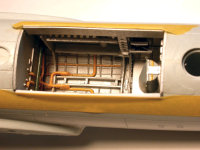
Amodel decided to go the whole hog on the landing gear bays! I mean there is so much detail in the bays that they could be like models themselves. Almost all the detail is represented with little missed at all. Of course again, you have to spend a good chunk of time in cleaning and test fitting all the parts.
I started work on the front wheel bay and painted the interior silver with yellow hydraulic pipes. I test fitted the parts numerous times and inserted them into the fuselage cavity repeatedly to see if all that cool stuff would ever have a chance to fit in there. Remember that the fuselage has many layers of fiberglass in it and it is very likely that you will have to sand down and possibly enlarge the cavities of your model.
Similarly I went to work on the real wheel bay of the Bison and used the same colors except I added green for the side walls. Amodel recommends Humbrol paints which look close to the pictures I have seen of the Monino Bison walk arounds but not quite right.
The instructions do not tell the modeler how to insert the wheel bays into the fuselage. You will probably find this useful if you are going to build a Bison. Start by insert the rear bulkhead inside the fuselage cavity first. Then twist and insert the rest of the wheel bay assembly. The bulkhead should be flush with the rear wall of the fuselage opening. You will do this exercise many times as you add the side walls and you will need to make sure that everything fits together as one unit in the end.
Once all the parts seemed to fit well, I ran superglue on the plastic and secured the plastic to the fiberglass fuselage.
Now what I need to do is build the front and rear landing gear and slide it in the bays to see how it all fits. The landing gear is also amazingly complex and detailed! After I assemble the front and rear landing gear I need to see how the model will sit and how to make it have the right look as it rests on the ground. I will not commit anything to glue yet. This will be done after the wings are on.
The intake and exhaust treatment is also quite complex providing complete trunking with turbine intake and exhaust fans. Of course with all these parts there are a lot of alignment concerns and I found out that this was not the only problem. Let's follow the process one step at a time.
I started first by putting together the intake portion of the nacelles. Make sure that you take into account that this assembly, when complete, will have to be open enough in the rear so it can match the cut provided on the fiberglass wing. The intake trunking provided for the front portion of the nacelles does not fit very well and it will leave gaps between it and the intake lips. No matter how much I tried to adjust the intake tubes they still left a gap. After the assembly dries up I will use 3M putty to fill the gaps and sand the intakes smooth. The results should be good and will look even better after priming and polishing.
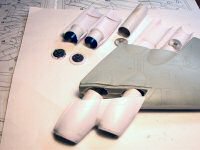
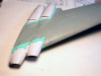
Next, I focused on trying to figure out how to put together the rear portion of the nacelles. The instructions show all the parts and where they go but no sequence is given. I started by taping the bottom portion of the nacelles and verifying that the fit was good. Then I test fitted the top portion of the nacelle and it just did not want to line up with its respective side of the bottom nacelle. This was not going to be a drop fit deal. I decided to super glue the bottom portion of the nacelle so it would provide a strong base to get things started and went on with assembling and test fitting the exhaust cans that would go inside the nacelles. A lot of sanding will be required to thin down the lips of the nacelles to give a better scale effect. The Bison exhausts are very well researched and show the staggered arrangement and provide a good representation when the model will be viewed from behind.
The engine nacelle work was pretty tedious and I decided to do some work on the fuselage and look at the engine problems and solutions with a fresh eye later. I first started working on the front fuselage plug and how it would fit the fuselage. The fit was pretty good on the top and bottom portions but left a big step on each side. I cannot blame Amodel for this because it is very likely that I caused the problem when I put the front plastic fuselage plug together. For my next Bison I will make sure that the rear cockpit bulkhead is trimmed down more so it does not alter the radius of the plastic fuselage. Again I used super glue to get the fuselage parts together. I repeated the same process for the rear fuselage plug and noted a similar step situation.
I used again 3M putty to get the step to disappear making sure that I would preserve the hump that is present on the top fuselage. The rear portion of the fuselage was also puttied to cover up the step and to blend the rear electronics housing to the tail. The putty was sanded down and finer putty was applied to smooth out the job. This work will be checked again after the whole model gets primed and inspected for any unwanted undulations and surface blemishes.
After the intake trunking was installed and adjusted as best as possible, I started trying to blend everything in with 3M Acryl Blue. Sanding the intakes revealed some small blemishes and gaps and I decided to use a big brush and apply liberal coats of Mr Surfacer 500 inside the trunks and around the nacelles at the joints. After sanding down the trunks with rolled sandpaper I was left with smooth intakes that need some very little attention towards the end of the building process and right before final priming and painting.
The next step was the hardest. How to fit all that in the wing and making it all look right.
The kit provides full intake trunks running the width of the wing. The long trunks inside the nacelles terminate to the steel color intake fan blades. The exhaust cans have their own fan blades which I painted gun metal gray. When the whole system is assembled it will look pretty realistic with no gaps and good detail to be seen when you peek through the intake and exhaust openings.
To glue the plastic intake assembly I had to use the Dremel tool and open up the receiving fiberglass tunnels. After that the assembly fit reasonably well leaving some gaps to fill later.
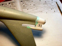
The rear assembly gave me more trouble and I had to do it in small steps. I started with the outboard engine cover which I super glued to the top of the wing. I did not glue it down to the corresponding bottom plastic nacelle part. I did the same thing with the inboard engine cover. When all was dry I slowly coaxed the top plastic nacelle part to come down and meet its corresponding bottom nacelle part making sure that the exhaust can was not sticking out or was too far in. Since there was tension from the uncooperative plastic I had to use super glue and accelerator to make sure that things would stay in place. The same process was followed for the more problematic inboard engine and this is when I wished I was born with three arms! Clamps came out and the super glue and when all looked to be squeezed into place I grabbed the zapper between my teeth and dropped some accelerator to the super glued joints. This was tough but it worked. You can see in the side view photo the inside of the wing and the complex and ambitious arrangements for a limited production kit.
When all the clamps were removed I used some more sandpaper to make sure that the exhaust cans were totally blended with the nacelles. The idea is to have the cans terminate exactly at the edge of the nacelle. This process of course removed some of the paint but this is going to be addressed later.
I also kept testing the wing fuselage joint to make sure that I was not violating the wing form as I was trying to squeeze in and superglue all the panels together.
The wing/nacelle joint will need work to eliminate gaps. Strips of styrene were used and filler super glue and in the end putty. All that will be blended in and primed later and rescribed. Oh, the joys of limited run kits! I then moved on to some necessary repair work around the wheel wells.
The inserting of the wheel wells together with removing the fiberglass wheel well blanking inserts left some gaps that did not look good to me. I decided to make everything straight and true with thick styrene strips which I super glued right at the edge of the fuselage cut outs and the wheel well side walls. With carefully sanding I managed to return this area back into shape. Some puttying later will complete this task. For a diversion from the difficult task I chose to put together the complex landing gear.
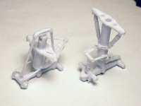
These arrangements are beautifully done. Very accurate and fun to put together. I did not glue everything in place and just snapped the major subassemblies together to gain perspective of another idea I have for the finished model. After I photograph the completed model on the ground I am going to have it suspended from the ceiling where I have my other huge models hanging out together. The main undercarriage of the Bison has a rotating mechanism which keeps the wheels at an angle to the fuselage. This means I will have to make some small modifications to pose the model in a landing configuration. The way Amodel has designed the kit makes this possible to achieve with some small mods to the landing gear.
Lastly, I feel that it makes sense to build the landing gear and insert it to the fuselage before the wings are on and the model gets too heavy. Once the model has the right stance the landing gear can be secured in place before the last assembly steps are completed.
<Insert 11-year time lapse here>
The Bison stayed in its box for a decade while other projects took priority. It was time to take it out again and honor the New Year resolution that has me finishing all the unfinished projects! The model parts were cleaned up again to freshen them up and to remind where I had I left off.
I used Mr. Surfacer 500 to prime the main parts and fix all the fiberglass blemishes. After polishing the parts with 3200 grit polishing cloth, I sprayed Mr Surfacer 1000 and polished all over again going to 12000 grit. I know that after the wings are on some of the polishing work will have to be repeated on the joints but at least I will not have to exert pressure on the outer wings and most of the fuselage.
The kit provides for dropped flaps which is nice as they are huge and prominent. The flap guides are not very well defined and need Dremeling as the fiberglass resin has interrupted the grooves.
The landing gear will look nice and busy but not very visible when the gear is inserted in the deep wheel wells.
The toughest part was to install the wings. I took a while to work the joints and achieve a good fit. I used black (rubber) cyanoacrylate glue to make sure I had a strong joint. I then puttied the joints and now there will be a little waiting period until I sand and polish the joints. Some rescribing will have to take place as well.
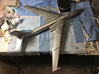
This model easily compares in size with my B-52s! It will be a pain to maneuver on my workbench as I am getting ready for painting. What I thought was going to take a little while to complete took much longer, much like everything else with this project.
All of the little detail parts need to be worked on individually as they are very rough. The small parts reminded me of BattleAxe or Mach2 kinds of jobs.
The air intakes on the top of the fuselage were rough with many molding defects and took many hours to reshape and refine.
As if that was not enough, I realized that the long antennas on the front of the fuselage did not match the receiving locating holes on the fuselage. They were too long and the attachment points were not in the right places. I used the 72nd scale plans to figure out lengths and positions. I still need to polish the antennas because I can see the joints where my sectioning took place.
The little antenna setup on the front of the cockpit was not useful and I had to replace the parts with Evergreen styrene rods cut to the right length.
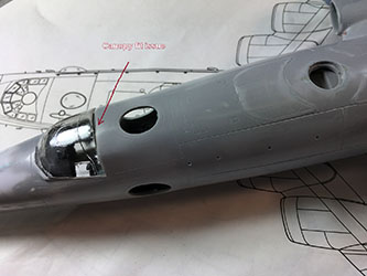
The Amodel canopy was another issue as it did not match the curvature of the fuselage. I had to force it carefully and hold it down with tape and glue it with the new Tamiya liquid cement. I was impressed how well it worked on the plastic. After the canopy was secured as best as possible, I sanded it in place, puttied it and primed until it was all conforming.
It was time to give the model a final wash and apply the Alclad II clear base. It took me two weeks between drying time and multiple coats. I wanted to make sure it would be really hard before handling the model for painting. Even with the Arizona heat, the base never stopped being tacky. The metal base paint went on and was left to dry for a few days.
Here is where things went funny. The Tamiya masking tape which is so benign did the following things. It lifted the paint and the primer and exposed the fiberglass underneath. In many areas the tackiness of the paint pulled the gum off the tape and made a sticky mess. After all this effort I was beside myself. I stepped away from this project until I could figure out what to do next. This is not an indictment against any product, it is just what happened to me. I had invested too much time in this kit, so I decided to get back to it.
I blocked off and sanded away the affected areas, re-polished and repainted but without the glossy undercoat. I removed the gum with Goo Gone which worked but messed with the metallic paint.
All of that was resprayed, and since this is a multi-hued paint job, I had to figure out how to mask without lifting the paint. I used wet newspaper and sticky note paper for masking. All that took forever, and I have no idea what I did wrong, but I am now essentially done. As a side note, the paint is still sticky a month later, so I handle the model with latex gloves. Something did not mingle well between the gloss undercoat and the metallic paints.
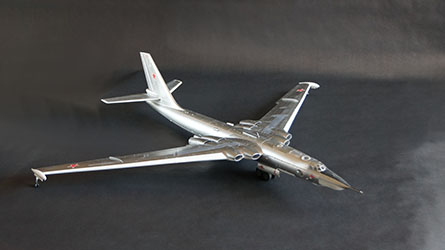
They say that when the model is on its landing gear, the completion is not too far away. Maybe but getting the beast on its landing gear was a total bison .. err.. I mean bear.! The model is very heavy, and the gear is barely able to handle it. More importantly, the goal is to have the all main wheels touch the ground but also have the outriggers touch as well. To do that, I removed all the protecting paper towels from the glass surface over my work bench and thus I got a perfect test surface. Once I had the main landing gear balanced, I used a set of calipers to figure out how high from the ground were the wingtips. I was not happy when I realized that the wingtips were a bit high. This is because I followed the instructions and the front landing gear sticks out of the fuselage a bit more than it should. When you build your Bison, make sure that you make the necessary mods and you sink the main landing gear strut deeper into the side rails. As such, my outriggers stick out a bit more than I like. The model is still balanced but the pictures show the outriggers closer to the pods when the plane is resting.
The rest of the work had to do with installing the huge flaps, all the tiny bits and all the paint touch ups.
The decals were a disaster. Not glossy at all, sensitive to handling but worst of all, they have a heavy opaque carrier film that looks awful on natural metal. Using decal softeners did not really work in hiding the film. I decided not to use all the stencils as much as I would have liked to. I have spare decals but they are in 1/48th scale and would not have worked.
All in all, I am glad this project is completed. Took me forever to get the will to finish it but it sure looks impressive in my collection. It will find its place right next to my B-52s and it sure looks just as big!
