Accurate Miniatures 1/48 SBD-3 Dauntless Build Review
By Stephen Sutton
| Date of Review | June 2004 | Manufacturer | Accurate Miniatures |
|---|---|---|---|
| Subject | Douglas SBD-3 Dauntless | Scale | 1/48 |
| Kit Number | 3411 | Primary Media | Styrene |
| Pros | Excellent recessed panels, superior interior details and decals | Cons | Dive brakes warped, one decal option, no twin mount .30 cal machine gun |
| Skill Level | Intermediate | MSRP (USD) | Out of Production |
Background
This SBD Dauntless kit represents the plane flown on 8 May 1942 by Ensign John Leppla and ARM3c John Liska during the Battle of the Coral Sea. Leppla was credited with four kills over a two-day period, while Liska claimed three. It is perhaps the best known and documented of all Dauntlesses to be flown during The Coral Sea action - 2-S-12 (BuNo 4547) of VS-2, USS Lexington (CV-2) during the Spring of 1942.
The Kit:
If you'd like to take a look at the kit as it comes out of the box, check out the in-box review
previously published here on Cybermodeler.
Construction:
To begin, you will need to follow the instructions very closely; the instructions are very detailed on how to install each kit part as well as very well illustrated for part installation locations.
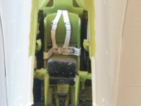
Step 1: The inside fuselage and side consoles where airbrushed with Model Master Acryl Interior Green FS 34151, then assembled. Injector marks found on the inside of the fuselage where hidden by the side consoles, very nice engineering by Accurate Miniatures. Next the details were painted out on the interior as per my color references found on the Internet. I chose to install the rear gunners bulkhead (E38) at this time as recommended by the instructions, I glued one side then I test fitted the two fuselage halves with masking tape and then I readjusted the rear gunners bulkhead for straightness. Then I glued the fuselage halves together, everything lined up perfectly, and no filler was required for the fuselage halves.
Step 2: The cockpit and gunners floor was assembled next, the most important thing here is to following the instructions. The instrument panel was painted interior green with flat black instrument panels and faces, the dials where painted with a sharp toothpick and the faces cleared with Future floor polish. I left the map table off for now. Everything was glued and allowed to dry overnight. The next day, all the small integrate interior pieces where airbrushed with interior green then they where carefully removed from the sprues. I followed all the recommendations in the instructions with no problems at all; tweezers and patience is an essential tool here.
Step 3: Interior components and seat belts are next, the pilots rear bulkhead and seat where airbrushed interior green, after they dried the kit decals have seat belts printed on them, I carefully cutout the seat belt with the backing paper then I glued the belt onto the seat with superglue. Next I test fitted the gunner’s radio equipment as per the instructions then I glued the pilots rear bulkhead and the gunner’s radio equipment.
Step 4: The rear gunner’s turret ring was airbrushed with interior green then all the very small parts where carefully removed from the sprues. The rear gunners seat belt was fashioned the same as the pilots seat. Everything was assembled and allowed to dry overnight before installation.
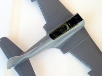
Step 5: The floor assembly and wings where painted interior green as per the instructions then the completed floor assembly was test fitted and glued to the bottom of the open fuselage and the lower wing half was glued to the bottom of the fuselage. The top wing halves where test fitted to the bottom wing halves, the outer wings where slightly warped so I carefully glued the wing halves as follows. I aligned and glued the wing tips, and then I worked my way inward and glued the edges as it secured the halves together with wooden cloths pins. After both wings halves had dried, a small gap was present between the fuselage and top wing roots, the step clearance between the wing root and fuselage where even. I corrected the small gaps with Tamiya Polyester putty.
The whole kit only had 3 very small sinkholes, 2 were found inward on each wing leading edge, and one was found on the aft fuselage upper wing root panel. All were filled with Tamiya Polyester putty and sanded. The horizontal stabilizers were assembled and installed with ease, and the arresting hook was secured to the rear fuselage.
Step 6: The nose assembly was assembled as per the instructions. The oil cooler was attached to the front of the fire wall. The oil coolers screen detail was very faint so I fashioned a piece of fish tank vacuum cleaner filter material to the front of the oil cooler. The Wright Cyclone R-1820-32 engine was assembled and painted. I painted the engine following the instructions, black pushrods, dark red ignition wires and grey crankcase, after checking my reference I should have painted the ignition wire harness aluminum, I instead painted the harness and wires dark red.
Step 7: The landing gear was assembled next, the tires, hubcaps and brake assemblies are all separate pieces; this makes painting the tires very easy. The landing gear assembly is designed to self align, so be sure to follow the assembly sequence. The pilot’s bomb release window was secured next with Model Master clear parts cement, then the window was masked with Woodland Scenics latex rubber. Allow everything to dry overnight.
Next the 1000 lb. bomb and the two 100 lb. bombs were assembled, painted, futured, decaled and set-aside.
The bomb fairing (E53) was found warped so I straightened out the fairing by dipping the part in microwaved very hot water and tweezers, extra caution should be taken when handling very hot water, you can get third degree burns from very hot water and you do not want to melt the styrene into a glob. Practice with different water temperatures until you get the results you require for straightening warped parts. Warped parts are usually a result of removing the styrene trees from the molds too quick, as was the case with sample copy. Ultimately I had no problem correcting the warped parts.
I then glued the bomb fairing to the center of the wing bottom. I will leave off the bombs, trapeze and wing bomb racks until the final assembly
Step 8: The dive brakes were assembled next; these parts were very thin and had some flash. The dive brakes were very warped, but they were corrected with the same procedures I described above. The dive brakes can be assembled fully closed, full open, or the landing position, I decided to assemble mine in the landing position. Care should be taken when removing the flap actuators from the sprues. I painted the inner dive brakes flat red and I painted the exterior surfaces to match the upper and lower wing colors, more to come on this!
The dive brakes and actuators were carefully glued in the landing position with all the lower dive brakes lowered.
Step 9: The cockpit details were next, headrest, hoisting cable, telescopic gun/bomb sight and radio direction finder loop were all painted and glued in place.
Step 10: Two canopy options are provided with the kit, closed or open, I picked the open option, I hate to waist all the detail on the closed canopy. All 6 canopy pieces where masked with Tamiya tape and then the frames were trimmed with a sharp number 11 hobby knife.
I then airbrushed all the canopies with a first coat of interior green, this allows the interior green to be seen from the inside. I next painted all 6 canopies with the final exterior color. I then glued the pilot’s windscreen with Model Master clear parts cement, white glue is a good substitute. The five other canopies were left off until final assembly.
Next the .30 caliber single mount machine gun was painted with Tamiya acrylic gunmetal, dry brushed with chrome silver and installed during the final assembly. Single mount .30 caliber machine gun? Yes, the Orders of the Day carried by the crew, noted the fact that these aircraft were carrying the single mount .30 cal machine guns in the rear position instead of the field modified twin .30 cal machine guns as were common on SBD-3 Dauntless aircraft. This kit only included the single mount machine gun. A twin-mounted machine gun would have been a nice addition to this kit.
The radio mast antenna was attached next and allowed to dry. Time to airbrush the Dauntless.
Painting and Marking
The paint and decal instructions give you only one option with a couple of modifications. A two-tone paint scheme is in order for the decal option that is given. All the top surfaces are painted Navy Blue Gray FS35189 and all the lower surfaces are painted Light Grey FS36440. The instructions include a great model paint reference chart. I prefer to use the Model Master Acryl line of paints, but Model Master does not make a Navy Blue Gray color, so more research was in order. I found a great downloadable Federal Standard color chip chart on the IPMS Stockholm website. I used this to mix my own blue grey color using Model Master Medium Grey FS35237 and I slowly adding Pactra Flat Blue until I achieved the color I wanted. After I already painted my blue gray mix, I discovered another acrylic color reference chart in the recently published book "Modeling Classic Combat Aircraft by Fine Scale Modeler on page 17, Navy Blue Grey are Gunze H42, Polly Scale 505088, Testor Acryl 4847.
I masked the cockpit by using the one-piece closed canopy that was included in the kit; I used latex rubber to secure it to the cockpit frame.
I airbrushed all the panel lines with acrylic flat black, and then I proceeded to paint each panel from the inside out with the final colors. I allowed everything to dry for 2 days, then I clear coated everything with Future. I allowed the Future to dry for at least 4 hours.
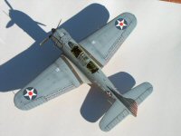
I choose the insignia used just prior to action in the Battle of the Coral Sea, the unit numbers (2-) were painted over at the time of action, as well as the tail stripes and red circles on the national insignia eventually were removed. I used the unit number and tail strips on this project. The decals were applied with warm water, and the excess carrier film was cut-a-way with scissors. Numerous applications of Model Master decal solvent were used to get the decals to conform to the panel lines and rudder ribs, then another coat of Future was used to seal the decals. I washed the entire airplane with black pastel chalk mixed in water and dishwashing soap; the excess wash was removed with clean Q-tips and water. Lastly, I final coated the entire airplane with Model Master Acryl flat clear.
Final Assembly
The propeller and hub was painted and installed, then the masks were removed from the canopies and the rear canopy (J105) was glued with MM clear parts cement over the DF antenna, then the next canopy (J103) frame had to be thinned it fit over the rear canopy (J105), I still had to glue and tape down the canopies on the cockpit frame, then the last two canopies where glued on top of the previous two canopies. The leading edge light lens, and the left wing landing light lens was glued in place. All the wing tip and navigation lights were first painted flat white then Tamiya clear, red, green, and orange were used in the proper locations. The .30 cal machine gun was attached and the radio antenna was rigged with my daughter's hair.
Summary
This was my first build of an Accurate Miniatures kit; it was truly a pleasure to build this very hi quality detailed kit. I enjoyed the fine cockpit details and the challenges of the interior parts and dive brakes, I would recommend this kit for the intermediate of expert builders, lots of attention to detail goes into this kit. I'm very pleased with my finished model.
Thanks to Accurate Miniatures for the review sample, I look forward to more kits.


