Kitty Hawk Models 1/48 Su-30MK Flanker Builder's Guide
By Michael Benolkin
| Date of Review | August 2020 | Manufacturer | Kitty Hawk |
|---|---|---|---|
| Subject | Su-30MK Flanker | Scale | 1/48 |
| Kit Number | 80169 | Primary Media | Styrene, Photo-Etch |
| Pros | Nice kit | Cons | See text |
| Skill Level | Experienced | MSRP (USD) | $79.99 |
Builder's Guide
For a brief discussion of this subject and a look at this kit out of the box, look here.
When Kitty Hawk recently released this kit, there were two other Flankers also released. I knew I wanted to do a full-up build of the single-seat Su-27 as well as one of the two-seaters, and while the Su-27UB and Su-30MK are almost identical, the latter has a different upper fuselage half with an opening for the positionable air refueling probe. I decided to build the Su-27UB in our quick-build format and in the course of doing that build, I discovered a number of glitches that needed to be pointed out. Since the Su-27UB uses most of the same parts as the Su-30MK, these glitches apply to this kit as well. Given that not many builders of the Su-30MK are going to read the Su-27UB review, I decided to create this builder's guide to share the relevant glitches and their solutions. Note that the images for this guide are taken fromt the Su-27UB (two-seater) review. If you want to read the Su-27UB quick-build review, you can look here.
Before we even start, just a reminder that the Kitty Hawk kits have the odd mold stubs that pop out of the strangest places as well as the odd bit of mold flash. Take the time to examine and clean up each part as this will significantly reduce your workload and enhance your enjoyment of this model later.
Step 1 - each of these K-36D ejection seats consist of 11 parts (plus the photo-etched pilot restraints not used here). These are nicely laid out and go together smoothly. If you're pondering resin aftermarket seats for your build, you might be wasting your money as these are the nicest K-36D seats I've seen in a kit.
Steps 2-4 - the two-place cockpit tub also goes together without any problems, as you can see here. All this subassembly needs to really stand out is a good paint session.
Step 5 - the instrument panels are added to the subassembly along with the glare shield for the rear cockpit.
I paused in the assembly process to test-fit the cockpit subassembly in the upper fuselage half. There are ribs molded into the fuselage sidewalls that engage the slots molded into the cockpit side consoles. This test will ensure that the side console overlay slots are aligned with the slots in the tub, or else nothing is going to fit here. Note that the front instrument panel isn't visible in this shot - the top edge of the front panel should be visible from here or else you'll have interference with the nose wheel well (ask me how I know this...).
Steps 6-7 - build up the radar avionics rack for the nose and the nosegear well.
Steps 8-9 - these steps are supposed to assemble the port and starboard intake truck/engine adaptors and are only four parts each. While these should have been a no-brainer to assemble, there's just no way to get the parts to align on their own. I jumped ahead to Step 11 where these are mounted into the lower fuselage half and I assembled each adaptor in its place. Don't forget to add the plugs (parts C59 and C65 while you're there.
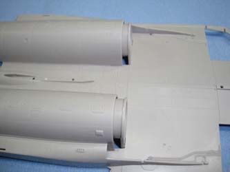
Steps 10-11 - the AL-31F engines go together almost effortlessly - you'll note the jungle of ejector pin stubs inside the engine casings and while most can be left alone, three in each engine are inside the afterburner throat which will be visible after assembly. I took a few minutes to get these three stubs mitigated. You'll note that I didn't waste time on the exterior details for these engines. They will not be visible with the access panels glued shut, so these parts are skipped. The engines are glued into the lower fuselage half.
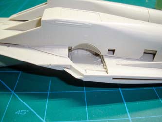
Steps 12-14 - the main wheel wells are assembled and glued into place on the lower fuselage half along with the nosewheel well. Note that in steps 12-13 (main wheel wells), parts C22 and C23 should be reversed. The cockpit is slid up into place and the radar avionics rack is mounted to the nose. Here is where the test-fitting really begins and it is here that I realized that the cockpit tub wasn't seated up all of the way. With that corrected...
the fuselage halves fall together with no gaps and are glued.
Without the intake trunks installed, you can clearly see the compressor faces of the two AL-31F engines. the nose wheel well and nose gear are assembled. If you opt to mount the nose access cover up (open), you'll have some nice details to show off.
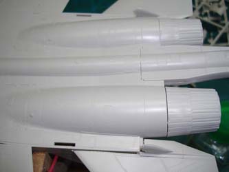
Skipping ahead to Steps 17-19, here is where we build up the intake trunks. The portside trunk has an opening on the side for the main wheel well that isn't fully opened (mold defect?), but using the starboard trunk as a pattern, I removed the extra plastic and fixed that problem. Building the intake ducts was no issue, though when I dry-fitted the intake trunks to the lower fuselage half, I wasn't happy with the duct alignment. Instead, I glued the ducts to the duct/engine adaptors, then overlaid the trunks and glued them into place. No matter what I did, there was still a slight gap between each trunk and the lower fuselage half that will need a little filler. Next time, I'll make further adjustments to the trunk/fuselage joint and if that doesn't work, I'll use filler here.
Step 20 - I mounted the radar bay access cover onto the nose (closed) as well as the gun and gun cover closed. The fit isn't as nice as most of the other joints in this kit, but if you're posing the avionics bay open, this won't be an issue. If not, a little sanding will be required here. The RWR fairings are mounted on the outboard sides of the intakes to complete this set.
Step 21-25 - the Su-27 series has an ingenious design feature where a knuckle on the main gear strut plugs into a mount located on the lower side of the fuselage to provide additional strength while operating from unimproved runways. The kit has the fairings for the knuckle receivers as parts A35 and A36, but the instructions indicate both are A36. Since these knuckle mounts are not interchangeable, I decided to build up one of the main gear struts so I could identify which receiver goes where. In Step 23, I was building the strut per the instructions and I was about to add the brakes and wheels when a blinding flash of the obvious struck: there is no axle molded to the main gear strut. Neither strut has an axle. None of the other two Flanker kits have axles on their main gear struts either.
I decided to fix the axle problem first. Rummaging through my plastic stock (old Evergreen from a store that went under years ago) I found styrene tubing of the right diameter (2.1mm) and drilled out the strut. The diameter of the new axle matches the kit wheels, so no mods are required there. That brings me back to the original question: which knuckle mount goes on which side of the airframe? That's when I discovered the REAL landing gear problem. I had built the gear strut assembly from Step 23, but when I attempted to dry mount it to the starboard side wheel well according to the instructions, it was backwards and it didn't fit on the port side either. That's when I discovered that the gear mount C13 should be C14. When I swapped those parts, I got good alignment on the port side main wheel well. The correct knuckle mount for the port side is A35. In Step 25 then, the gear strut built in step 23 goes in the portside well and the strut from step 24 goes into the starboard side.
Here's the magic moment in any aircraft build when the model is standing on its own. Now that we're through the landing gear challenge (and I skipped ahead to steps 27-28 for the nose gear), step 26 is where we add wings and stabilators. The wing and wing/fuselage joint are things of beauty. The stabilators are also well done though the stabilator fairings D1 and D2 are reversed in the instructions. The stabilator hinge pins are just a millimeter too close to the adjacent edge of the stabilators so the pins won't fit onto the fuselage hinges. Take a flat microfile to the stabilator edge to widen the gap between it and the pin and it will fit and move perfectly. Note the dorsal speed brake from Step 22 doesn't quite fit closed. I tried to make some adjustments which did help close it to what you see, but it is either going to take more effort or be left open in my next build.
Another glitch in the instructions identify the hydraulic actuator mounts on the horizontal stabilators as parts D3 and D6 - they're D15 and D18, and from what I can tell it doesn't matter which one goes port or starboard.
Steps 26-30 - These final steps wrap up the build which include the vertical stabs, canopy, IRST nose overlay, and radome. The radome fits perfectly. The stabilator actuator fairings on the bottom aft end of the vertical stabs are problematic, but I added the kit parts as indicated in the instructions, then trimmed the stabilator actuator fairings flush (flat) with the bottom of the vertical stab. Since the outboard fairings are not long enough and since the vertical stabs are otherwise identical, I simply swapped the stabs to put the longer fairings outboard.
A word of caution here: the landing gear struts are scale thickness which isn't bad, coupled with the multi-part assemblies in the load-bearing struts, the landing gear isn't not very strong. I put the model into a cradle to keep the gear and other extremities safe while working on the model.
I decided to skip the gear doors and pylons, as well as antennae and probes to call this quick-build done. The IRST overlay, windscreen and canopy are dry-fitted here as I want to keep them as spares in case I need them for the Su-27 build. Overall, the engineering in this kit is some of the best Kitty Hawk has done considering how well the fuselage halves, wings, and cockpit all went together. Now that I know the bugs in the landing gear, I'm going to consider drilling out the struts and inserting pins to strengthen the load-bearing struts and replace the plastic main gear 'knuckle' with brass to make the kit's main gear as rugged as the full-scale aircraft.
One reader pointed out that the Scale Aircraft Conversions' metal Su-27 landing gear for the HobbyBoss kit is of a very similar design as the Kitty Hawk gear and may be adapted. The gear struts for the Academy Su-27 would require more substantial modifications to use those struts. I ordered a set of the SAC struts for the HB kit and while they are indeed similar in layout as the KH kit, they have the same two-part main strut layout, but where the KH joints actually mate together, the SAC struts have stubs that will not fit into the receiving holes. These may be stronger when (if they can be) assembled, but they're going to be more work than simply drilling and inserting a brass wire through the kit strut. Don't bother with the SAC struts.
Since we usually see test-builds of these kits online before they're released, I am going to assume that the Wuhan virus and associated shutdown of the Kitty Hawk factory while everyone was locked down is the reason why they decided to release these kits without proper testing. Had they run through any of the three kits (they all share most of the same parts), they would have found the bug in the main wheel well, missing axles, and dyslexic parts callouts. Had a test build and corrective revisions taken place, these kits would have easily been the best of their releases to date. Even so, I still enjoyed building this kit, so much that I'm going to do a full build of at least one of the other two.
My sincere thanks to Kitty Hawk Models for this review sample!


