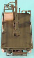
Glencoe 1/15 M274 Mechanical Mule Build Review
By Michael Benolkin
| Date of Review | August 2006 | Manufacturer | Glencoe |
|---|---|---|---|
| Subject | M274 Mechanical Mule | Scale | 1/15 |
| Kit Number | 5401 | Primary Media | Styrene |
| Pros | Simple kit, excellent refresher for the true art of 'modeling' | Cons | |
| Skill Level | Basic | MSRP (USD) | $9.98 |
Background
After the Korean War, the US Army defined a new concept for cross-country mobility - the Platform. Developed by Willys, the makers of the immortal Jeep, the M274 was a lightweight powered flatbed that featured four wheel drive (4WD) AND four wheel steering.
Weighing in at 900 pounds, the M274 could easily be airlifted around the battlefield, and its 16 horsepower engine could propel the vehicle up to 25 mph. This was the precursor to the 4WD All-Terrain Vehicles (ATV) that are popular work and play vehicles today.
The M274 could mount a 106mm recoilless rifle. It measured in at 119 inches long and 50 inches wide. The Mechanical Mule was used by the US Army as well as by some NATO and other allied nations.
The Kit
If you'd like to take a look at the kit as it comes out of the box, check out the in-box review
previously published here on Cybermodeler.
Construction
I found myself in a rut with a project that was taking too long and was more frustrating than gratifying. You've had those as well, the models either get tossed or put back into a box for a 'rainy day'. If you're like me, you've got enough rainy day projects to cover the next great flood. So rather than just stare at that project any longer, I set it aside and grabbed a 'quickie' project just to 'cleanse the palette'. What could be easier than Glencoe Models' 1/15 Mechanical Mule?
There are only a handful of parts to the whole project, yet this wasn't going to be an overnight build. In fact, I was looking at something that would help me dust off some good old-fashioned modeling skills! I also decided that since I didn't know much about the M274 nor had I ever seen one in person, I would simply build the model as-is - no aftermarket parts and no major surgery to correct any perceived detail problems. With that understanding, I set off to build this kit.
There are several things to understand about Glencoe's models. First, you'll likely never hear of a new-tool project from Glencoe Models. Many of these molds date back to the 1960s as these are some of the better classic molds that were rescued from the scrap heap when a model company either discontinued the kit or simply went out of business. Second, the molds were designed decades ago when kits were expected to have some working features. Finally, this kit retails at less than $10 USD and can be found cheaper than that.
The downside of older molds is flash. When molds get worn, they begin to leak molten styrene between the plates which becomes very thin plastic extending from parts or even interconnecting parts. This is called flash and simply requires a little extra time to trim away and clean up the flashed parts. So as I go through each construction step, I do lots of dry-fitting of parts and subassemblies to understand where things go and to address fit problems caused by flash, seam/mold lines, ejector pin marks, etc.
The first step is to assemble the recoilless rifle. The first real step is to glue those two barrel halves together and somehow get a straight gun out of those warped halves. This turned out to be a simple refresher on stress management - in this case applying the appropriate stress/strain on key parts of the rifle. To do this, I used Tamiya thin cement on the first several inches of the rifle and used a clamp to hold that end in place. I continued cementing the next several inches and added a second clamp to the center of the rifle, then finished the cementing and clamped the other end. Eyeballing the result showed a nicely formed S-shaped barrel. Here we go back to basic modeling skills: release the middle clamp, align the barrel and replace the clamp. Remove each end clamp and continue adjusting. Remove only one clamp at a time. You're not bending styrene here, you are working with cement that hasn't dried yet, so the barrel halves are slipping as you release the clamps and make your adjustments. Despite the odd alignment of the barrel when I started, the process of aligning the barrel with still-wet cement only took a few minutes before I had a straight barrel and I could set the result aside to fully dry.
Once the gun is dry and solid, I decided to open up the end of the barrel. There is a 'cap' over the barrel end as molded. I simply drilled a pilot hole in the center of the barrel 'cap' and used a Dremel router bit to open up the hole. I simply hand-twisted the bit into the hole until it had opened up the diameter to full caliber. Had I used a file or other method prior to assembling the barrel, I ran the risk of a misaligned hole or perhaps a hole that was more oval shaped. This technique created a nice round open barrel.
Next comes the four wheels. The instructions have you assemble each of the four wheels and add the brake/axle part (parts 6 or 10). The instructions do not refer to the four disks in the kit that were supposed to go inside the wheels. These disks would cement to the ends of the axles and allow the wheels to turn freely. Even after discovering this, I left the disks out as I didn't want my kit to roll off. I assembled the wheel halves, but left off the brake/axle parts as you'll find it easier to build and paint the kit with the wheels off for now.
Now comes the chassis. Like the barrel, if this assembly comes out with a twist after it dries, the completed model will look rather odd. I took the two chassis tubular frames, cemented the three crossmembers into place, then set the assembly under weight on glass to get a proper alignment. When it was dry, I dry-fit the chassis to the platform (part 26) and found that everything lined up just fine.
Setting the platform aside for now, we assemble both of the main axles with the steering arms and brake/axle parts. When completed, the brake/axle parts will steer in unison. Both the front and rear wheels are steerable on most versions of the M274. The axles are glued into place per the instructions. Next comes the steering linkage parts which tie the front and rear steering mechanisms together and provide a linkage to the steering wheel.
For those of us 'more senior' modelers, we'll remember this modeling technique all too well. Heat up the tip of the screwdriver and melt the tops of each of the steering hinges as indicated by the instructions When this is finished, you can steer the front and rear wheels with the steering wheel. Toylike? Perhaps, but the feature doesn't detract from the model and is rather fun to mess with after completion.
The four-cylinder engine is installed on the chassis along with the drive shaft. The engine is a simple two-piece affair that also represents the transmission, but a little paint will bring out some of the details.
The platform was where I spent time experimenting. The underside of the platform had circular pads molded along the outer perimeter frame. These provided a solid footing for the ejector pins when this rather complex part (for its day) was released from the mold. These would have been okay as-is on the underside of the platform, but I wanted to put my Mission Models Micro Chisel
through its paces. I trimmed away the pads until all that was left was the perimeter frame. I did gouge the surface a little until I got the hang of trimming away the hunks of plastic. I then used Gunze Sangyo's Mr. Dissolved Putty to fill in a few remaining ejector pin marks and the few self-inflicted scars. I also applied Mr. Dissolved Putty to a few sink marks and gaps on the chassis as well.
The platform mounts onto the chassis and fuel tank is assembled and stashed under the left side of the platform. This step is rounded out with the foot rest frame, foot pedals, shift/brake levers, steering wheel and shaft, and rear engine guard.
The driver's seat is the only part that I didn't use 'out of the box' as the kit came from the generation where the backs of the seats were molded open (no back). I simply added a piece of sheet styrene to the back of the driver's seat to box in the rear, and the seat was set aside until painting.
Painting and Finishing
I washed the subassemblies to clean away the oils, dust and debris (not to mention cat hair). I used sanding sticks to clean up any excess putty and the kit was ready for paint.
I painted all of the parts Tamiya NATO Black as the base coat. When this was dry, I painted the chassis/body and recoilless rifle Tamiya Olive Green. I also painted the wheels Olive Green, leaving the tires NATO Black. The driver's seat was painted Tamiya Khaki. Once all of this was dry, I weathered the tires with some mud and dust to give them some appearance of recent use.
The wheels were then mounted onto the axles with Tamiya Liquid Cement so that they would not roll. With cats in the house, if it moves, it dies. The driver's seat and recoilless rifle were finally installed, completing this build.
Conclusion
This was a fun little project. Even at 1/15 scale, this is a small model and looks good on my shelf. I have since looked up the M274 online and realized where I could have added a few more details, etc., but that would have defeated the purpose of this project - this was a recreational build. That's okay, I have another Glencoe M274 stashed away...
I really enjoyed the opportunity to put my skills to work that I haven't used in a while. As I said, the project isn't complex, but you'll get out what you put into it. You can build the kit in an evening, but the result certainly won't look as nice.
This kit is definitely recommended as a fun build or even an AMS project.


